
REGDOC-2.4.3, Nuclear Criticality Safety, Version 1.1
View or download as a PDF [148 pages, 2.2 MB]
Preface
This regulatory document is part of the CNSC’s safety analysis series of regulatory documents, which also covers deterministic safety analysis and probabilistic safety assessment. The full list of regulatory document series is included at the end of this document and can also be found on the CNSC’s website.
Regulatory document REGDOC 2.4.3, Nuclear Criticality Safety sets out requirements for nuclear criticality safety and provides guidance on how those requirements may be met. It provides information for the prevention of criticality accidents in the handling, storage, processing and transportation of fissionable materials and the long term management of nuclear waste.
This document clarifies the minimum physical constraints and limits on fissionable materials in order to ensure nuclear criticality safety during the construction, operation, decommissioning, or abandonment of the licensed facility and with respect to the handling, storing, processing and transportation of certain fissionable materials. It applies to operations with fissionable materials outside nuclear reactors, except for the assembly of these materials under controlled conditions (such as in critical experiments).
Key principles and elements used in developing this document are consistent with national and international standards. Some sections of this document are extracted from certain standards from the American National Standards Institute (ANSI), with permission of the publisher, the American Nuclear Society (ANS). Where necessary, the text has been adapted to make it applicable to Canada’s international obligations to the International Atomic Energy Agency (IAEA) and consistent with CNSC’s regulatory requirements.
This document is Version 1.1. It supersedes Version 1, which was published in February 2019. A document that shows the changes made to REGDOC‑2.4.3, Version 1 is available from the CNSC upon request.
For information on the implementation of regulatory documents in the licensing basis, and on the graded approach, see
REGDOC-3-5-3, Regulatory Fundamentals.
The words “shall” and “must” are used to express requirements to be satisfied by the licensee or licence applicant. “Should” is used to express guidance or that which is advised. “May” is used to express an option or that which is advised or permissible within the limits of this regulatory document. “Can” is used to express possibility or capability.
Nothing contained in this document is to be construed as relieving any licensee from any other pertinent requirements. It is the licensee’s responsibility to identify and comply with all applicable regulations and licence conditions.
Table of Contents
- 1. Introduction
- 2. Nuclear Criticality Safety in Operations with Fissionable Materials Outside Reactors
- 3. Criticality Accident Alarm System
- 4. Use of Borosilicate-Glass Raschig Rings as a Neutron Absorber in Solutions of Fissile Material
- 5. Safety in Conducting Subcritical Neutron Multiplication Measurements In Situ
- 6. Nuclear Criticality Safety in the Storage of Fissile Materials
- 7. Criteria for Nuclear Criticality Safety Controls in Operations with Shielding and Confinement
- 8. Nuclear Criticality Control and Safety of Plutonium-Uranium Fuel Mixtures Outside Reactors
- 9. Use of Soluble Neutron Absorbers in Nuclear Facilities Outside Reactors
- 10. Nuclear Criticality Safety Control of Selected Actinide Nuclides
- 11. Criticality Safety Criteria for the Handling, Transportation, Storage, and Long term Waste Management of Reactor Fuel Outside Reactors
- 12. Administrative Practices for Nuclear Criticality Safety
- 13. Nuclear Criticality Safety Training
- 14. Use of Fixed Neutron Absorbers in Nuclear Facilities Outside Reactors
- 15. Nuclear Criticality Safety Based on Limiting and Controlling Moderators
- 16. Nuclear Criticality Accident Emergency Planning and Response
- Appendix A: Normal and Credible Abnormal Conditions
- Appendix B: Calculation Methods Yielding keff
- Appendix C: Example: Validation of a Calculational Method
- Appendix D: Detector Placement
- Appendix E: Fuel Unit Handling, Storage, and Transportation—Criticality Safety Considerations
- Appendix F: Moderators and Moderating Materials
- Appendix G: Example of a Partial Description of a Nuclear Criticality Safety Program for a Fuel Storage Facility
- G.1 Template of contents of nuclear criticality safety program
- G.2 Identifying the requirements
- G.3 Sample procedure for criticality accident sequence assessment
- G.3.1 Assessing the effectiveness of the CSC
- G.3.2 Risk score evaluation summary
- G.3.3 Accident summary and likelihood index assignment for Table G-1
- Accident Sequence / Identifier
- Initiating Event (a1) and Enabling Event (a2) (if applicable)
- Preventive Safety Parameter 1 or CSC 1 Failure/Success (b)
- Preventive Safety Parameter 2 or CSC 2 Failure/Success (c)
- Preventive Safety Parameters or CSC Failure/Success (d1, d2...)
- Likelihood Index / Risk Score* T uncontrolled/ controlled (e)
- Consequence Evaluation Reference
- Comments and Recommendations
- G.3.4 Determination of failure frequency index numbers in Table G-2
- G.3.5 Determination of failure probability index numbers in Table G-3
- G.3.6 Determining management measures for CSC
- G.3.7 Risk-informed review of CSC
- Glossary
- References
1. Introduction
1.1 Purpose
This regulatory document sets out requirements for nuclear criticality safety and provides guidance on how those requirements may be met. It provides information for the prevention of criticality accidents in the handling, storage, processing, and transportation of fissionable materials and the long term management of nuclear waste.
1.2 Scope
This document clarifies the minimum physical constraints and limits on fissionable materials in order to ensure nuclear criticality safety during the construction, operation, decommissioning, or abandonment of the licensed facility and with respect to the handling, storing, processing and transportation of certain fissionable materials.
This document also provides guidance on how the requirements for nuclear criticality safety may be met. The information set out in this document applies to operations with fissionable materials outside nuclear reactors, except for the assembly of these materials under controlled conditions (such as in critical experiments).
Note: In the context of nuclear criticality safety, the term "water" refers to light water unless otherwise noted. Where the term "ordinary water" is used in the chemical context, it refers to light water.
1.3 Relevant legislation
The following provisions of the Nuclear Safety and Control Act (NSCA) and the regulations made under the NSCA are relevant to this document:
- subsection 24(4) of the NSCA states that "No licence may be issued, renewed, amended or replaced – and no authorization to transfer one given – unless, in the opinion of the Commission, the applicant (a) is qualified to carry on the activity that the licence will authorize the licensee to carry on; and (b) will, in carrying on that activity, make adequate provision for the protection of the environment, the health and safety of persons and the maintenance of national security and measures required to implement international obligations to which Canada has agreed"
- subsection 24(5) of the NSCA states that "A licence may contain any term or condition that the Commission considers necessary for the purposes of this Act"
- paragraphs 3(1)(i) and (j) of the General Nuclear Safety and Control Regulations state that "An application for a licence shall contain the following information:
(i) a description and the results of any test, analysis or calculation performed to substantiate the information included in the application;
(j) the name, quantity, form, origin and volume of any radioactive waste or hazardous waste that may result from the activity to be licensed, including waste that may be stored, managed, processed or disposed of at the site of the activity to be licensed, and the proposed method for managing and disposing of that waste" - paragraph 12(1)(f) of the General Nuclear Safety and Control Regulations states that "Every licensee shall...(f) take all reasonable precautions to control the release of radioactive nuclear substances or hazardous substances within the site of the licensed activity and into the environment as a result of the licensed activity"
- subsection 13(1) of the Radiation Protection Regulations states that "Every licensee shall ensure that the effective dose received by and committed to a person described in column 1 of an item of the table to this subsection, during the period set out in column 2 of that item, does not exceed the effective dose set out in column 3 of that item"
- paragraph 5(i) of the Class I Nuclear Facilities Regulations states that "An application for a licence to construct a Class I nuclear facility shall contain the following information...: (i) the effects on the environment and the health and safety of persons that may result from the construction, operation and decommissioning of the nuclear facility..."
- paragraph 6(h) of the Class I Nuclear Facilities Regulations states that "An application for a licence to operate a Class I nuclear facility shall contain the following information...: (h) the effects on the environment and the health and safety of persons that may result from the operation and decommissioning of the nuclear facility..."
- paragraph 7(f) of the Class I Nuclear Facilities Regulations states that "An application for a licence to decommission a Class I nuclear facility shall contain the following information...: (f) the effects on the environment and the health and safety of persons that may result from the decommissioning"
- paragraphs 14(3)(c) and (d) of the Class I Nuclear Facilities Regulations state that "Every licensee who decommissions a Class I nuclear facility shall keep a record of
(c) the manner in which and the location at which any nuclear or hazardous waste is managed, stored, disposed of or transferred;
(d) the name and quantity of any radioactive nuclear substances, hazardous substances and radiation that remain at the nuclear facility after completion of the decommissioning" - subsection 2(1) of the Packaging and Transport of Nuclear Substances Regulations, 2015 states that these regulations "apply to the packaging and transport of
(a) prescribed equipment; and
(b) nuclear substances, including- (i) the design, production, use, inspection, maintenance and repair of packaging and packages for nuclear substances, and
- (ii) the preparation, consigning, handling, loading, carriage, storage during transport, receipt at final destination and unloading of packages and unpacking of their contents"
The Nuclear Fuel Waste Act and the Nuclear Liability and Compensation Act may also apply to operations with fissionable materials.
1.4 National and international standards
Key principles and elements used in developing this document are consistent with national and international standards.
Some sections of this document are extracted or adopted from the following standards from the American National Standards Institute (ANSI), with permission of the publisher, the American Nuclear Society (ANS). Where necessary, the text has been adapted to make it applicable to Canada’s international obligations to the International Atomic Energy Agency (IAEA) and consistent with CNSC’s regulatory requirements. These sections are independent (not all sections apply to any one facility), and are presented in order according to the ANSI/ANS numerical identification, as follows:
- ANSI/ANS-8.1-2014, Nuclear Criticality Safety in Operations with Fissionable Materials Outside Reactors
- ANSI/ANS-8.3-1997 (reaffirmed in 2017), Criticality Accident Alarm System
- ANSI/ANS-8.5-1996 (reaffirmed in 2017), Use of Borosilicate-Glass Raschig Rings as a Neutron Absorber in Solutions of Fissile Material
- ANSI/ANS-8.6-1983 (reaffirmed in 2017), Safety in Conducting Subcritical Neutron-Multiplication Measurements In Situ
- ANSI/ANS-8.7-1998 (reaffirmed in 2007), Nuclear Criticality Safety in the Storage of Fissile Materials
- ANSI/ANS-8.10-2015, Criteria for Nuclear Criticality Safety Controls in Operations With Shielding and Confinement
- ANSI/ANS-8.12-1987 (reaffirmed in 2016), Nuclear Criticality Control and Safety of Plutonium-Uranium Fuel Mixtures Outside Reactors
- ANSI/ANS-8.14-2004 (reaffirmed in 2016), Use of Soluble Neutron Absorbers in Nuclear Facilities Outside Reactors
- ANSI/ANS-8.15-2014 (reaffirmed in 2019), Nuclear Criticality Safety Control of Selected Actinide Nuclides
- ANSI/ANS-8.17-2004 (reaffirmed in 2019), Criticality Safety Criteria for the Handling, Storage, and Transportation of LWR Fuel Outside Reactors
- ANSI/ANS-8.19-2014, (reaffirmed in 2019), Administrative Practices for Nuclear Criticality Safety
- ANSI/ANS-8.20-1991 (reaffirmed in 2020), Nuclear Criticality Safety Training
- ANSI/ANS-8.21-1995 (reaffirmed in 2019), Use of Fixed Neutron Absorbers in Nuclear Facilities Outside Reactors
- ANSI/ANS-8.22-1997 (reaffirmed in 2016), Nuclear Criticality Safety Based on Limiting and Controlling Moderators
- ANSI/ANS-8.23-2019, Nuclear Criticality Accident Emergency Planning and Response
- ANSI/ANS-8.24-2017, Validation of Neutron Transport Methods for Nuclear Criticality Safety Calculations
This document is consistent with:
- IAEA Safety Standards, Safety of Conversion Facilities and Uranium Enrichment Facilities, IAEA SSG-5, 2010
- IAEA Safety Standards, Safety of Nuclear Fuel Cycle Facilities Specific Safety Requirements, IAEA SSR‑4, 2017 [1]
- IAEA Safety Standards, Safety of Uranium Fuel Fabrication Facilities, IAEA SSG-6, 2010 [2]
- IAEA Safety Standards Series No. GS-R-2, Preparedness and Response for a Nuclear or Radiological Emergency, Safety Requirements, 2002 [3]
- Health Canada, Canadian Guidelines for Intervention during a Nuclear Emergency, H46-2/03-326E, 2003 [4]
- CSA Group, CSA Standard N292.2-13 (reaffirmed in 2018), Interim dry storage of irradiated fuel [5]
- CSA Group, CSA Standard N292.1-16, Wet storage of irradiated fuel and other radioactive materials [6]
- ISO Standard 1709, Nuclear energy – Fissile materials – Principles of criticality safety in storing, handling, and processing, 1995 (reviewed in 2018) [7]
- ISO Standard 7753, Nuclear energy – Performance and testing requirements for criticality detection and alarm systems, 1987 (reviewed in 2018) [8]
- ISO Standard 11320, Nuclear criticality safety – Emergency preparedness and response, 2011 (reviewed in 2018)
- ISO Standard 14943, Nuclear fuel technology – Administrative criteria related to nuclear criticality safety, 2004 (reviewed in 2013) [9]
- IEC Standard 60860, Radiation Protection Instrumentation – Warning Equipment for Criticality Accidents, 2014 [10]
2. Nuclear Criticality Safety in Operations with Fissionable Materials Outside Reactors
Some parts of this section are extracted from ANSI/ANS-8.1-2014, Nuclear Criticality Safety in Operations with Fissionable Materials Outside Reactors, with permission of the publisher, the American Nuclear Society. The text may have been adapted to make it applicable to Canada’s international obligations to IAEA and consistent with CNSC’s regulatory requirements.
2.1 Introduction
Operations with some fissionable materials introduce risks of a criticality accident resulting in a release of radiation that can be lethal to nearby personnel. However, experience has shown that extensive operations can be performed safely and economically when proper precautions are exercised. The few criticality accidents that have occurred show frequency and severity rates far below those typical of non nuclear accidents.
This favourable record can be maintained only by continued adherence to good operating practices such as those embodied in this document; however, the document, by itself, cannot establish safe processes in an absolute sense.
Good safety practices should recognize economic considerations, but the protection of operating personnel and the public must be the dominant consideration.
2.2 Scope
Generalized basic criteria are presented and limits are specified for some single fissionable units of simple shape containing 233U, 235U, or 239Pu but not for multiunit arrays.
Criteria are stated for establishing the validity and areas of applicability of any calculational method used in assessing nuclear criticality safety.
This section does not include the details of administrative controls, the design of processes or equipment, the description of instrumentation for process control, nor detailed criteria to be met in transporting fissionable materials.
2.3 Nuclear criticality safety practices
Operations with fissionable materials shall meet the requirements of this document and should follow the recommendations of this document.
2.3.1 Categorization of operations with fissionable materials
2.3.1.1 Exempted quantity of fissionable materials
An exempted quantity of fissionable materials in the licensed site is defined as an inventory of fissionable materials, as follows:
- less than 100 g of 233U, or 235U, or 239Pu, or of any combination of these three isotopes in fissionable material combined in any proportion; or
- an unlimited quantity of natural or depleted uranium or natural thorium, if no other fissionable materials nor significant quantities of graphite, heavy water, beryllium, or other moderators more effective than light water are allowed in the licensed site (Note: see section 11.3 for additional information on short- or interim-term storage [dry or wet] of spent fuel); or
- less than 200 kg in total of natural or depleted uranium or natural thorium if some other fissionable materials are present in the licensed site, but the total amount of fissile nuclides in those fissionable materials is less than 100 g
Licensed sites with exempted quantities of fissionable materials are exempt from the requirements and recommendations of this document.
2.3.1.2 Small quantity of fissionable materials
A small quantity of fissionable materials in the licensed site is defined as an inventory of fissionable materials, which:
- exceeds the exempt limits listed in section 2.3.1.1; but
- does not exceed the following limits:
- 500 g of 233U, or 700 g of 235U, or 450 g of 239Pu, or 450 g of any combination of these three isotopes. These limits apply to operations with plutonium, 233U, or uranium enriched in 233U or 235U. These limits do not apply if significant quantities of graphite, heavy water, beryllium, or other moderators more effective than light water are present; or
- 80% of the appropriate smallest critical mass
This document is partially applicable, as further specified in section 2.3.1.4, to licensed sites operating with small quantities of fissionable materials.
2.3.1.3 Large quantity of fissionable materials
A large quantity of fissionable materials in the licensed site is defined as an inventory of fissionable materials that exceeds the limits listed in section 2.3.1.2.
This document is applicable to licensed sites operating with large quantities of fissionable materials.
Note that a licensed site containing a large quantity of fissionable materials may be subject to the Nuclear Liability and Compensation Act.
2.3.1.4 Nuclear criticality safety program relative to categorization
A nuclear criticality safety program shall be developed and maintained in the licensed site to meet the CNSC nuclear criticality safety requirements and to support its safe operation. The extent of the program depends on the category of operations with fissionable materials:
- licensed sites involved in operations with small quantities of fissionable materials, as defined in section 2.3.1.2, shall develop and maintain a reduced-scope program based on the applicable sections of this document, taking into account that the requirements of sections 2.3.2.2, 2.3.2.9, 3, 11, 12.5, and 12.7 are not applicable. The program shall ensure that the entire process remains subcritical such that inadvertent criticality cannot occur.
- licensed sites involved in activities with large quantities of fissionable materials, as defined in section 2.3.1.3, shall develop and maintain a program based on the applicable sections of this document and the CNSC requirements. The content of a program are described in section 12.8 of this document.
Applicability of the criticality safety program to separate areas of the licensed site should be based on the categorizations in section 2.3.1.
2.3.2 Program practices
2.3.2.1 Responsibilities
Management shall clearly establish responsibility for nuclear criticality safety. Supervisors should be made as responsible for nuclear criticality safety as they are for production, development, research, or other functions. Each individual, regardless of position, shall be made aware that nuclear criticality safety in their work area is ultimately their responsibility. This may be accomplished through training and periodic retraining of all operating and support personnel. Nuclear criticality safety does not differ in any intrinsic way from industrial safety, and good managerial practices apply to both.
Management shall provide personnel skilled in the interpretation of data pertinent to nuclear criticality safety, and familiar with operations, to serve as advisors to supervisors. These specialists should be, to the extent practicable, administratively independent of process supervisors.
Management shall establish the criteria to be satisfied by nuclear criticality safety controls. Distinction may be made between shielded and unshielded facilities, and the criteria may be less stringent when adequate shielding and confinement assure the protection of personnel.
2.3.2.2 Process analysis
Before a new operation with fissionable material is begun, or before an existing operation is changed, it shall be determined that the entire process will be subcritical under both normal and credible abnormal conditions that have frequency of occurrence equal to or greater than 10-6 per year [5, 6]. Examples of such conditions are given in appendix A.
- An adequate upper subcritical limit (USL) shall be established and justified such that:
- if calculational methods are applied to predict neutron multiplication factors for safety assessment:
- the USL is calculated using the formulas presented in appendix B, and
- a minimum administrative margin of subcriticality, as presented in the formulas for calculating the USL, is 5% in neutron multiplication factor [5, 6]
- if calculational methods are not applied to predict neutron multiplication factors for safety assessment:
- the USL is 500 g of 233U, or 700 g of 235U, or 450 g of 239Pu, or 450 g of any combination of these three isotopes. These limits shall be applied only when the surrounding materials, including other nearby fissionable materials, can be shown to increase the effective multiplication factor (keff) no more than it would be increased if the unit were enclosed by a contiguous layer of water of unlimited thickness; or
- otherwise, the minimum administrative margin of subcriticality shall be 20% of the critical mass [5, 6]
- if calculational methods are applied to predict neutron multiplication factors for safety assessment:
- The established adequate USL shall be maintained under all normal and credible abnormal conditions, and:
- all credible abnormal conditions having frequency of occurrence equal to or more than 10-6/year are identified and assessed; and
- the frequency of occurrence for the identified credible abnormal conditions is clearly demonstrated using quantitative or semi-quantitative methods (see appendix G)
- It shall be demonstrated that adequate mitigation measures are in place such that off site consequences of a representative nuclear criticality accident, as calculated from the start of the accident, do not violate criteria established as a trigger for a temporary public evacuation by the following international standard and national guidance [5, 6]:
- IAEA Safety Standards Series No. GS-R-2, Preparedness and Response for a Nuclear or Radiological Emergency, Safety Requirements, Annex III, Subsection III 2 [3]
- Health Canada, Canadian Guidelines for Intervention during a Nuclear Emergency, H46-2/03-326E [4]
Note: A representative nuclear criticality accident is as defined in section 16.4.
- In item 3, above (the list of requirements to demonstrate the mitigation of off site consequences of a representative nuclear criticality accident), the licensee may exclude any of the following independent sets of abnormal conditions:
- an external event that leads to a criticality accident with frequency of occurrence less than 10-7/year; or
- process deviations for which there is a convincing argument, given by physical laws, that they are not possible, or are unquestionably extremely unlikely; the validity of the argument must not depend on any feature of the design or materials controlled by the facility’s system of criticality safety controls, or management measures
Considering the impact of external events on the facility, the frequency of occurrence of the impact should be calculated by evaluating the vulnerable impact areas; i.e., areas where fissionable materials are processed or stored. To evaluate the consequences of the impact or the adequacy of the design to resist the impact, only realistic impact scenarios should be considered, which might require the knowledge of various factors such as angle of impact for aircraft crash, etc [2]. If there are no historic records or other scientific grounds to estimate impact of a natural phenomena event at the low limit frequency of occurrence (10-7/year), the impact of the event that is the most severe reasonably possible (sometimes referred to as probable maximum natural phenomena event) may be treated as the bounding event.
2.3.2.3 Written procedures
Operations to which nuclear criticality safety is pertinent shall be governed by written procedures.
All persons participating in these operations shall understand and be familiar with the procedures.
The procedures shall specify all parameters that they are intended to control. They should be such that no single, inadvertent departure from a procedure can cause a criticality accident.
2.3.2.4 Materials control
The movement of fissionable material shall be controlled. Appropriate material labelling, signs, and area posting shall be maintained specifying material identification and all limits on parameters subject to procedural control.
2.3.2.5 Equipment control
Prior to starting a new or modified process or processing line, it shall be ascertained that all equipment is consistent in dimension and material with the assumptions that were made to ensure subcriticality [7].
2.3.2.6 Quality management program
A quality management (QM) program that meets the applicable requirements of ANSI/ASME-NQA-1-2015, Quality Assurance Requirements for Nuclear Facility Applications [11], CSA-N286-12, Management system requirements for nuclear facilities [12], or equivalent, shall be established to implement the activities specified in this document.
Records shall be maintained according to the QM program to demonstrate that the facility and its equipment were constructed according to the design specifications. The licensee shall define a formal design change procedure as part of their QM program, so that all modifications made to the facility or to the facility’s processes or procedures during all stages of the facility life cycle are accurately recorded and their impact assessed with respect to nuclear criticality safety [1]. These QM measures are expected to be an integral part of the facility’s overall QM program.
Throughout this document, "quality assurance" is considered to be one element of the quality management system.
2.3.2.7 Operational control
Deviations from procedures and unforeseen alterations in process conditions that affect nuclear criticality safety shall be reported to management and shall be investigated promptly. When available, the information about incidents and events in other installations of the same type shall also be investigated and lessons learnt shall be considered. Possible improvements in criticality safety practices or equipment shall be considered and action shall be taken to prevent recurrence [1, 7].
2.3.2.8 Operational reviews
Operations shall be reviewed frequently (at least annually) to verify that procedures are being followed and that process conditions have not been altered in any way that would affect the applicable nuclear criticality safety evaluation (NCSE). These reviews shall be conducted in consultation with operating personnel, by individuals who are knowledgeable in nuclear criticality safety and who, to the extent practicable, are not immediately responsible for the operation.
2.3.2.9 Emergency procedures
Emergency procedures shall be prepared and approved by management. On site and off site organizations that are expected to respond to emergencies shall be made aware of conditions that might be encountered, and they should be assisted in preparing suitable procedures governing their responses.
2.3.3 Technical practices
The effective multiplication factor (keff) of a system depends on the mass, distribution, and nuclear properties of the fissionable materials and all other materials with which they are associated.
Nuclear criticality safety is achieved by controlling one or more parameters of the system within subcritical limits and by allowances for process contingencies. Prevention of criticality may be exercised through:
- physical restraints, such as confining a solution to a cylindrical vessel with diameter no greater than a specified value, or controlling the spacing between material and equipment [7]
-
use of instrumentation
During normal operations, a number of parameters shall be measured and controlled to prevent a criticality, such as keeping a fissile concentration below a specified value by devices that measure concentration and prevent its buildup in a chemical system. The measuring devices shall be of high integrity and calibrated against known standards [1].
- chemical means, such as prevention of conditions that allow precipitation
- reliance on a natural or credible course of events, such as a process whose nature is to keep the density of uranium oxide less than a specified fraction of maximum theoretical density
- administrative procedures, such as requiring that a mass not exceed an established limit
- other means
Nuclear criticality safety shall be ensured by means of preventive measures that are, as far as reasonably achievable, established in the design; that is, by engineered nuclear criticality safety controls.
2.3.3.1 Controlled parameters
All controlled parameters and their limits shall be specified. The influence of variations in these parameters on the keff of the system shall be understood.
2.3.3.2 Availability and reliability
The licensee shall ensure that the necessary levels of availability and reliability are maintained for nuclear criticality safety controls, as established by the process analysis for normal and credible abnormal conditions.
The following principles shall be incorporated as appropriate to attain the required availability and reliability of engineered nuclear criticality safety controls [1].
Double contingency principle
For the prevention of criticality by means of design, the double contingency principle shall be the preferred approach. For application of the double contingency principle, the design for a process should incorporate sufficient factors of safety to require at least two unlikely, independent and concurrent changes in process conditions before a criticality accident is possible.
Redundancy
The principle of redundancy should be applied as an important design principle for improving the reliability of systems important to safety. Multiple sets of equipment that cannot be tested individually should not be considered as redundant. The adopted degree of redundancy shall also reflect the potential for undetected failures that could degrade reliability [1].
Single failure criterion
The design shall ensure that no single failure can result in a loss of capability of engineered nuclear criticality safety controls to perform their intended safety function.
Independence
The principle of independence (as functional isolation, or as physical separation by distance, barriers, or layout of process equipment or components) shall be applied, as appropriate, to enhance the reliability of systems, in particular with respect to common cause failures. Multiple sets of equipment that cannot be tested individually should not be considered as redundant. The adopted degree of redundancy shall also reflect the potential for undetected failures that could degrade reliability [1].
Diversity
The principle of diversity can enhance reliability and reduce the potential for common cause failures. It should be adopted on safety significant systems wherever appropriate and reasonably practicable [1].
Fail-safe design
Where practicable, the fail safe principle should be applied to components important to safety; i.e., if a system or component should fail, the facility should pass into a safe state without a requirement to initiate any protective or mitigating actions [1].
Testability
All engineered nuclear criticality safety controls shall be designed and arranged so that:
- their safety function can be adequately inspected and tested
- the engineered nuclear criticality safety controls can be maintained, as appropriate before commissioning and at suitable and regular intervals thereafter in accordance with their importance to safety
If it is not practicable to provide adequate testability of a component, the safety analysis should take into account the possibility of undetected failures of such equipment [1].
2.3.3.3 Geometry control
Where practicable, reliance should be placed on equipment design in which dimensions are limited rather than on administrative controls. Full advantage may be taken of any nuclear characteristics of the process materials and equipment. All dimensions and nuclear properties on which reliance is placed shall be verified prior to the beginning of operations, and control shall be exercised to maintain them.
Process areas where criticality control vessels contain significant quantities of nuclear materials in liquid form should be equipped with alarms to prevent overfilling and with drip trays of appropriate capacity and critically safe configuration.
2.3.3.4 Neutron absorbers
Reliance may be placed on neutron-absorbing materials, such as cadmium and boron that are incorporated in process materials, or in equipment, or in both. Control shall be exercised to maintain their continued presence with the intended distributions and concentrations. Where practicable, the incorporation of solid neutron absorbers as permanent, integral parts of equipment is more desirable than the use of neutron absorbers in solution, because of the processing controls required to demonstrate the continued presence of dissolved absorbers.
Neutron-absorbing materials are most effective for neutrons of thermal energy and care shall be exercised to ensure that their effectiveness is not seriously reduced in operational or accident conditions, which might change the fissile assembly into one characterized by neutrons of intermediate or high energy [7].
2.3.3.5 Subcritical limit
Where applicable data are available, subcritical limits shall be established on bases derived from experiments, with adequate allowance for uncertainties in the data. In the absence of directly applicable experimental measurements, the limits may be derived from calculations made by a method shown by comparison with experimental data to be valid in accordance with section 2.3.4.
2.3.3.6 Neutron reflection
Where applicable, neutron reflection shall be considered as a parameter for criticality control. The most effective neutron reflector commonly encountered in handling and in processing fissionable material is water of thickness sufficient to yield maximum nuclear reactivity. However, careful consideration shall be given to systems where significant thicknesses of other common structural materials (e.g., wood, concrete, steel), which may be more effective neutron reflectors than water, may be present. For some situations, the reflection provided by personnel may be important [7] (the material content of the human body can provide significant moderating capability [appendix F]).
2.3.3.7 Neutron interaction
Consideration shall be given to neutron interaction between units when at least two units containing fissionable material are present. It is possible to reduce neutron interaction to acceptable proportions either by spacing units, by insertion of suitable neutron-moderating and absorbing materials between units, or by some combination of these methods [7].
2.3.4 Validation of a calculational method
Suitable calculational methods for determining the subcritical state of a system shall be selected and justified in accordance with an applicable quality assurance standard. The methods vary widely in basis and form, and each has its place in the broad spectrum of situations encountered in the nuclear criticality safety field. However, the general procedure to be followed in establishing validity is common to all. Refer to appendix C for an example of validation of a calculational method.
2.3.4.1 Establishment of bias
Bias shall be established by correlating the results of critical and exponential experiments with results obtained for these same systems by the calculational method being validated.
When no experimental data are available, establishment of the bias for a calculational method is not possible and these requirements cannot be satisfied. Validation of a calculational method by comparing the results with those of another calculational method, for example, is unacceptable.
Commonly, the correlation is expressed in terms of the values of keff calculated for the experimental systems at the critical state, in which case the bias is the deviation of the calculated values of keff from unity. However, other physical states and parameters may be used; in the absence of critical experiments data, the results from techniques that can be demonstrated to measure the amount by which a system is subcritical may be used. The bias serves to normalize a method over its area (or areas) of applicability so that it will predict critical conditions within the limits of the uncertainty in the bias. Generally, neither the bias nor its uncertainty is constant; both are expected to be functions of composition and other variables.
2.3.4.2 Bias trends
The area (or areas) of applicability of a calculational method may be extended beyond the range of experimental conditions over which the bias is established by making use of the trends in the bias. Where the extension is large, the method should be supplemented by other calculational methods to provide a better estimate of the bias, and especially of its uncertainty in the extended area (or areas), and to demonstrate consistency of computed results.
2.3.4.3 Bias uncertainties
The uncertainty in the bias shall contain allowances for uncertainties in the experimental conditions, for lack of accuracy and precision in the calculational method, and for extension of the area (or areas) of applicability. After allowances are made for the accuracy and precision of the method and for the bias and uncertainty, a margin in the keff or other correlating parameter shall be applied that is sufficiently large to ensure that conditions (calculated by the method to be subcritical by this margin) will actually be subcritical. Like the bias and its uncertainty, this margin may vary with composition and other variables.
2.3.4.4 Computer dependence
If the calculational method involves a computer program, checks shall be performed to confirm that the mathematical operations are performed as intended. Any changes in the computer program shall be followed by reconfirmation that the mathematical operations are performed as intended.
2.3.4.5 Consistency with measurements
Nuclear properties, such as cross sections, used in calculational method should be consistent with experimental measurements of these properties.
2.3.4.6 Validation report
A written report of the validation shall be prepared. This report shall:
- describe the method with sufficient detail, clarity, and lack of ambiguity to allow independent duplication of results
- identify the experimental data and list the parameters derived from the data for use in the validation of the method
- state the area (or areas) of applicability
- state the bias and uncertainties over the area (or areas) of applicability
- state the margin of subcriticality over the area (or areas) of applicability, including the justification for the adequacy of the margin of subcriticality
- state the upper subcritical limit (see appendix B for details)
2.4 Single-parameter limits for fissile nuclides
If single-parameter limits for 233U, 235U, and plutonium given in sections 2.4.1, 2.4.2, 2.4.3, and 2.4.4 are used, an adequate administrative margin of subcriticality shall be applied to ensure compliance with section 2.3.2.2.
These limits were calculated by methods satisfying the requirements of section 2.3.4. A limit shall be applied only when the surrounding materials, including other nearby fissionable materials, can be shown to increase the effective multiplication factor (keff) no more than it would be increased if the unit were enclosed by a contiguous layer of water of unlimited thickness. A limit may be applied to a mixture of fissile nuclides by considering all components of the mixture to be the one with the most restrictive limit.
Process specifications shall incorporate margins to protect against uncertainties in process variables and against a limit being accidentally exceeded.
2.4.1 Uniform aqueous solutions
Any one of the limits of Table 2-1 is applicable provided a uniform aqueous solution is maintained. It is therefore implied that the concentrations of the saturated solutions are not exceeded.
The 239Pu limits apply to mixtures of plutonium isotopes, provided that the concentration of 240Pu exceeds that of 241Pu and provided that 241Pu is considered to be 239Pu in computing mass or concentration. Less restrictive limits are provided in section 2.5.3 for plutonium isotopic compositions containing appreciable concentrations of 240Pu.
The limit on atomic ratio is equivalent to the limit on solution concentration, but the ratio limit may also be applied to non aqueous solutions, regardless of the chemical form of the fissile nuclide.
| Parameter | Subcritical limit for fissile solute | ||||
|---|---|---|---|---|---|
| 233UO2F2 [13] |
233UO2(NO3)2 [13] |
235UO2F2 [14] |
235UO2(NO3)2 [14] |
239Pu(NO3)4 [14] |
|
| Mass of fissile nuclide, kg | 0.54 | 0.55 | 0.76 | 0.78 | 0.48 |
| Diameter of cylinder of solution, cm | 10.5 | 11.7 | 13.7 | 14.4 | 15.4 |
| Thickness of slab of solution, cm | 2.5 | 3.1 | 4.4 | 4.9 | 5.5 |
| Volume of solution, L | 2.8 | 3.6 | 5.5 | 6.2 | 7.3 |
| Concentration of fissile nuclide, g/L | 10.8 | 10.8 | 11.6 | 11.6 | 7.3 |
| Atomic ratio of hydrogen to fissile nuclide (a) | 2390 | 2390 | 2250 | 2250 | 3630 |
| Areal density of fissile nuclide, g/cm2 | 0.35 | 0.35 | 0.40 | 0.40 | 0.25 |
(a) Lower limit
2.4.2 Aqueous mixtures
The areal densities of Table 2-1 are independent of the chemical compound and are valid for mixtures that have density gradients, provided the areal densities are uniform.
The subcritical mass limits for 233U, 235U, and 239Pu in mixtures that might not be uniform are 0.50, 0.70, and 0.45 kg, respectively, and are likewise independent of compound [13, 14, 15].
2.4.2.1 Enrichment limits
Table 2-2 contains 235U enrichment limits for uranium compounds mixed homogeneously with water with no limitations on mass or concentration.
| Compound | Subcritical Limit: wt% 235U[14] |
|---|---|
| Uranium metal | 0.93 |
| UO2, U3O8, or UO3 | 0.96 |
| UO2(NO3)2 | 1.96 |
2.4.3 Metallic units
The enrichment limit for uranium and the mass limits given in Table 2-3 apply to a single piece having no concave surfaces. They may be extended to an assembly of pieces, provided that there is no interspersed moderation.
The 233U and 235U limits apply to mixtures of either isotope with 234U, 236U, or 238U provided that 234U is considered to be 233U or 235U, respectively, in computing mass [14]. The 239Pu limits apply to isotopic mixtures of plutonium, provided that the concentration of 240Pu exceeds that of 241Pu and all isotopes are considered to be 239Pu in computing mass [15]. Density limits may be adjusted for isotopic composition.
| Parameter | Subcritical limit | ||
|---|---|---|---|
| 233U[13] | 235U[14] | 239Pu[15 | |
| Mass of fissile nuclide, kg | 6.0 | 20.1 | 5.0 |
| Cylinder diameter, cm | 4.5 | 7.3 | 4.4 |
| Slab thickness, cm | 0.38 | 1.3 | 0.65 |
| Uranium enrichment, wt% 235U | – | 5.0 | – |
| Maximum density for which mass and dimension limits are valid, g/cm3 | 18.65 | 18.81 | 19.82 |
| Parameter | 233UO2[13] | 233U3O8[13] | 233UO3[13] | 235UO2[14] | 235U3O8[14] | 235UO3[14] | 239PuO2[15] |
|---|---|---|---|---|---|---|---|
| Mass of fissile nuclide, kg | 10.1 | 13.4 | 15.2 | 32.3 | 44.0 | 51.2 | 10.2 |
| Mass of oxide, (a) kg | 11.7 | 16.0 | 18.7 | 37.2 | 52.8 | 62.6 | 11.5 |
| Cylinder diameter, cm | 7.2 | 9.0 | 9.9 | 11.6 | 14.6 | 16.2 | 7.2 |
| Slab thickness, cm | 0.8 | 1.1 | 1.3 | 2.9 | 4.0 | 4.6 | 1.4 |
| Maximum bulk density (b) for which limits are valid, g/cm3 |
(a) These values include the mass of any associated moisture up to the limiting value of 1.5% by weight.
(b) w represents the quantity of water, in wt %, in the oxide.
| Parameter | 233UO2[13] | 233U3O8[13] | 233UO3[13] | 235UO2[14] | 235U3O8[14] | 235UO3[14] | 239PuO2[15] |
|---|---|---|---|---|---|---|---|
| Mass of fissile nuclide, kg | 23.4 | 30.5 | 34.7 | 88 | 122 | 142 | 27 |
| Mass of oxide, (b) kg | 27.0 | 36.6 | 42.4 | 102 | 146 | 174 | 30 |
| Cylinder diameter, cm | 11.9 | 14.8 | 16.3 | 20.4 | 26.0 | 28.8 | 12.6 |
| Slab thickness, cm | 1.6 | 2.2 | 2.6 | 5.8 | 8.0 | 9.3 | 2.8 |
(a) These are half the maximum bulk densities of Table2-4.
(b) These values include the mass of any associated moisture up to the limiting value of 1.5% by weight.
2.4.4 Oxides
The limits in Tables 2-4 and 2-5 apply only if the oxide contains no more than 1.5% water by weight. The mass limits apply to a single piece having no concave surfaces. They may be extended to an assembly of pieces, provided that there is no additional interspersed moderation.
The mass limit is given equivalently as mass of nuclide and as mass of oxide (including moisture). It is emphasized that the limits in Tables 2-4 and 2-5 are valid only under the specified bulk density restrictions. Note that, particularly for UO3, material densities in excess of the full densities of Table 2-4 may be possible and hence that the limits of Table 2-4 may not be valid for highly compacted oxides. With water content limited to 1.5%, the enrichment limit of Table 2-2 for uranium oxides is increased to 3.2% 235U.
2.5 Multiparameter control
Although the single-parameter limits are adequate for many purposes, they are inconveniently and uneconomically small for many others. Simultaneous limitation of two or more parameters results in a less restrictive limit for the one of interest.
If multi-parameter limits for 233U, 235U, and plutonium given in sections 2.5.1, 2.5.2, 2.5.3, and 2.5.4 are used, an adequate administrative margin of subcriticality shall be applied to ensure compliance with section 2.3.2.2.
A few particularly useful examples are given in Subsections 2.5.1 through 2.5.4. All were calculated by methods satisfying section 2.3.4. These limits shall be applied only when the surrounding materials can be shown to increase the effective multiplication factor (keff) no more than it would be increased if the unit were enclosed by a contiguous layer of water of unlimited thickness. General guidance for multiparameter control may be found in the technical literature [16, 17, 18, 19].
Note that process specifications shall incorporate margins to protect against uncertainties in process variables and against a limit being accidentally exceeded.
2.5.1 Uranium metal- and uranium oxide- water mixtures at low 235U enrichment
An application of multiparameter control is control of both the 235U enrichment of uranium and one of the parameters of section 2.4. Parameter limits [20] applicable to aqueous systems containing uranium metal or uranium oxide (UO2), regardless of the size and shape of metal or oxide pieces, are specified as functions of enrichment in Tables VI-VIII of [20] which give, respectively, the mass of 235U, the cylinder diameter, the slab thickness, the volume, and the areal density.
2.5.2 Aqueous uranium solutions at low 235U enrichment
A similar application of multiparameter control is control of both 235U enrichment and one of the parameters of Table 2-1, together with the maintenance of a uniform aqueous solution. Table 2-6 lists parameter limits for uniform aqueous solutions of uranium where the enrichment is controlled within the stated limit. Concentrations of saturated solutions, which are here taken to be 5 molar for UO2F2 solutions and 2.5 molar for UO2(NO3)2 solutions, shall not be exceeded.
| Parameter | Enrichment, wt% 235U | Subcritical limit | |
|---|---|---|---|
| UO2F2 | UO2(NO3)2 | ||
| Mass, kg 235U | 10.0 | 1.07 | 1.47 |
| 5.0 | 1.64 | 3.30 | |
| 4.0 | 1.98 | 6.50 | |
| 3.0 | 2.75 | (b) | |
| 2.0 | 8.00 | (b) | |
| Cylinder diameter, cm | 10.0 | 20.1 | 25.2 |
| 5.0 | 26.6 | 42.7 | |
| 4.0 | 30.2 | 58.6 | |
| 3.0 | 37.4 | (b) | |
| 2.0 | 63.0 | (b) | |
| Slab thickness, cm | 10.0 | 8.3 | 11.9 |
| 5.0 | 12.6 | 23.4 | |
| 4.0 | 15.1 | 33.7 | |
| 3.0 | 20.0 | (b) | |
| 2.0 | 36.5 | (b) | |
| Volume, L | 10.0 | 14.8 | 26.7 |
| 5.0 | 30.6 | 111.0 | |
| 4.0 | 42.7 | 273.0 | |
| 3.0 | 77.0 | (b) | |
| 2.0 | 340.0 | (b) | |
| Concentration, g U/L | 10.0 | 123.0 | 128.0 |
| 5.0 | 261.0 | 283.0 | |
| 4.0 | 335.0 | 375.0 | |
| 3.0 | 470.0 | (b) | |
| 2.88 | (b) | 594.9 (a) | |
| 2.0 | 770.0 | (b) | |
| 1.45 | 1190.0 (a) | (b) | |
(a)Saturated solution
(b)Data not available
2.5.3 Uniform aqueous solutions of Pu(NO3)4 containing 240Pu
Reliance on, and hence control of, the isotopic concentration of 240Pu in plutonium permits greater limits for Pu(NO3)4 solutions than are listed in Table 2-1. Where plutonium, in addition, is intimately mixed with natural uranium, limits are even greater. Limits for this case are included in section 8, Nuclear Criticality Control and Safety of Plutonium-Uranium Fuel Mixtures Outside Reactors. However, the amount of the increase is dependent on 241Pu concentration.
| Parameter | Subcriticality Limit | ||
|---|---|---|---|
| ≥5 wt% 240Pu ≤1 wt% 241Pu |
≥15 wt% 240Pu ≤6 wt% 241Pu |
≥25 wt% 240Pu ≤15 wt% 241Pu |
|
| Mass, kg Pu | 0.57 | 0.78 | 1.02 |
| Cylinder diameter, cm | 17.4 | 19.5 | 21.3 |
| Slab thickness, cm | 6.7 | 8.0 | 9.2 |
| Volume, L | 10.0 | 13.6 | 17.2 |
| Concentration, g Pu/L | 7.8 | 8.9 | 10.2 |
| H/Pu, (a) | 3400 | 2980 | 2600 |
| Areal density, g Pu/cm2 | 0.28 | 0.34 | 0.4 |
(a)Atomic ratio of hydrogen to plutonium
2.5.4 Aqueous mixtures of plutonium containing 240Pu
Subcritical mass limit for plutonium as PuO2 in aqueous mixtures, which might be non-uniform, where 240Pu and 241Pu are subject to the three pairs of restrictions on isotope composition of Table 2-7, are, in increasing order of 240Pu concentration, 0.53, 0.74, and 0.99 kg, respectively [15].
3. Criticality Accident Alarm System
Some parts of this section are extracted from ANSI/ANS-8.3-1997 (Reaffirmed in 2017), Criticality Accident Alarm System, with permission of the publisher, the American Nuclear Society. The text may have been adapted to make it applicable to Canada’s international obligations to IAEA and consistent with CNSC’s regulatory requirements.
3.1 Introduction
Guidance for the prevention of criticality accidents in the handling, storing, processing, and transporting of fissionable materials is presented in section 2 of this document. In most operations with fissionable materials the risk of inadvertent criticality is very low; however, this risk cannot be eliminated. Where a criticality accident may lead to an excessive radiation dose, it is important to provide a means of alerting personnel and a procedure for their prompt evacuation, or other protective actions to limit their exposure to radiation.
3.2 Scope
Section 3 (this section) applies to all operations involving fissionable materials in which inadvertent criticality can occur and cause personnel to receive an excessive radiation dose.
This section does not apply to detection of criticality events where no excessive radiation dose to personnel is credible, nor to nuclear reactors or critical experiments. This document does not include details of administrative actions or of emergency response actions that occur after alarm activation.
3.3 General principles
3.3.1 General
The purpose of an alarm system is to reduce risk to personnel. Evaluation of the overall risk should recognize that hazards may result from false alarms and subsequent sudden interruption of operations and relocation of personnel.
Subject to the evaluation of the overall risk described above, a criticality alarm system meeting the requirements of this regulatory document shall be installed in areas where:
- inadvertent criticality can occur, and
- excessive radiation dose to personnel is credible should the inadvertent criticality occur
Where alarm systems are installed, emergency procedures shall be maintained. Guidance for the preparation of emergency plans is provided in section 16, Nuclear Criticality Accident Emergency Planning and Response.
Process equipment used in areas from which immediate evacuation is required should be so designed that leaving the equipment does not introduce significant risk.
3.3.2 Coverage
3.3.2.1 Evaluation of criticality alarm systems
In view of the requirement of List Item 1 in section 3.3.1, the need for criticality alarm systems shall be evaluated:
- for all activities involving 233U, 235U, and 239Pu, in which the inventory of fissionable materials (containing any of these three isotopes) exceeds 500 g of 233U, 700 g of 235U, 450 g of 239Pu, or 450 g of any combination of these three isotopes
- for all activities involving fissionable materials in which neutron moderators or reflectors more effective than light water are present, or unique material configurations exist such that critical mass requirements may be less than the subcritical mass limits listed above, or
- for all activities in which inventory of fissionable materials exceeds 80% of the appropriate critical mass if subcritical mass limits listed above are not applicable, or not appropriate
This evaluation shall be performed for all activities in which the inventory of fissionable materials in individual unrelated areas exceeds the subcritical mass limits noted above.
For this evaluation, individual areas may be considered unrelated when the boundaries between the areas are such that there can be no transfer of materials between areas [8], the minimum separation between material in adjacent areas is 10 cm, and the areal density of fissile material averaged over each individual area is less than 50 g/m2. This stipulation applies only to 233U, 235U, and 239Pu.
3.3.2.2 Installation of criticality alarm systems
A criticality alarm system meeting the requirements of this section shall be installed in areas where personnel would be subject to an excessive radiation dose. For this purpose, the maximum fission yield integrated over the duration of the accident may be assumed not to exceed 2.0 x 10¹⁹ fissions. The basis for a different maximum fission yield shall be documented.
If criticality accidents of lesser magnitude than the minimum accident of concern given in section 3.4.6 are of concern, then other detection methods (e.g., audible personnel dosimetry) should be considered. These other detection methods are not considered to be criticality alarm systems and are not covered by section 3 of this document.
3.3.2.3 Detection of criticality accidents
In areas in which criticality alarm coverage is required, a means shall be provided to detect a criticality accident and to signal that prompt protective action is required.
3.3.3 Criticality alarm
Criticality alarm signals shall be for prompt evacuation or other protective actions. The criticality alarm signals should be uniform throughout the system. The signals shall be distinctive from other signals or alarms that require a response different from the response necessary in the event of a criticality accident.
The signal generators shall be automatically and promptly actuated upon detection of a criticality accident.
After actuation, the signal generators shall continue to function as required by emergency procedures, even if the radiation falls below the alarm point, and at least long enough to allow people to reach their evacuation assembly points and perform the procedures to account for all personnel. Manual resets, with limited access, should be provided outside areas that require evacuation [8].
A means for manual actuation of the criticality alarm signal may be provided.
For all occupied areas where personnel protective action is required in the event of criticality accident detection, the number and placement of criticality alarm signal generators shall be such that the signals are adequate to notify personnel promptly throughout those areas.
The audio generators should produce an overall sound pressure level of at least 75 dB, but not less than 10 dB above the maximum ambient noise level typical of each area for which audio coverage is to be provided.
Because excessive noise levels can be injurious to personnel, the audio generators should not produce an A-weighted sound level in excess of 115 dB at the ear of an individual.
In areas with very high audio background or mandatory hearing protection, visual signals or other alarm means should be considered.
3.3.4 Dependability
Consideration shall be given to the avoidance of false alarms. This may be accomplished by providing reliable single detector channels or by requiring concurrent response of two or more detectors to initiate the alarm.
In redundant systems, failure of any single channel shall not prevent compliance with the detection criterion specified in section 3.4.6.
A means that will not cause an evacuation should be provided to test the response and performance of the alarm system [8].
Portable instruments may be used in special situations to augment an installed criticality accident alarm system. Examples of such situations include alarm system maintenance or testing, evacuation drills, activities in areas not normally occupied by personnel, or other special operations.
Where portable instruments are used to meet the intent of section 3 of this document, the usage shall be evaluated to determine appropriate criteria are met. Criteria for such use of portable instruments shall be specified in procedures.
Process areas in which activities will continue during power outages shall have emergency power supplies for alarm systems, or such activities shall be monitored continuously with portable instruments.
Adequate sensitivity of the alarm system to respond to the minimum accident of concern is addressed in section 3.4.7.
Detectors shall not fail to trigger an alarm when subjected to intense radiation exceeding 1000 Gy/h. Compliance with this provision may be demonstrated by a test of sample detectors or by a manufacturer’s test of production samples [8].
3.4 Criteria for system design
3.4.1 Reliability
The system shall be designed for high reliability and should use components that do not require frequent servicing (such as lubrication or cleaning).
The system should be designed to minimize the effects of non-use, deterioration, power surges, and other adverse conditions. The design of the system should be as simple as is consistent with the objectives of ensuring reliable actuation of the criticality alarm signal and avoidance of false alarms.
3.4.2 System vulnerability
All components of the system should be located or protected to minimize damage in case of fire, explosion, corrosive atmosphere, or other extreme conditions. The system should be designed to minimize the potential for failure (including false alarm) due to human error. Major system components should be labelled.
3.4.3 Seismic tolerance
The system should remain operational in the event of seismic shock equivalent to the site-specific design basis earthquake, or to the equivalent value specified by the National Building Code of Canada that applies to the structure.
3.4.4 Failure warning
The system should be designed to provide a visible or audible warning signal at some normally occupied location to indicate system malfunction or the loss of primary power.
3.4.5 Response time
The system shall be designed to produce the criticality alarm signal within one half second (0.5 s) of detector recognition of a criticality accident.
3.4.6 Detection criterion
A basic consideration in the design of a criticality accident alarm system is the definition of the lower magnitude of the event size to be detected, termed the "minimum accident of concern".
Criticality alarm systems shall be designed to respond immediately to the minimum accident of concern. In situations where there is only nominal shielding, the definition of minimum accident of concern provided in the glossary should be used. The basis for a different definition of minimum accident of concern shall be documented.
Document LA-13638 [21] describes nuclear criticality accidents that occurred during processing or handling of fissionable material. Consideration of these events resulted in the definition of the minimum accident of concern provided in the glossary.
3.4.7 Sensitivity
Criticality alarm systems shall be designed so that alarm actuation shall occur as a result of the minimum duration of the transient. It may be assumed that the minimum duration of the radiation transient is one millisecond (1 ms).
The alarm trip point shall be set low enough to detect the minimum accident of concern. The alarm trip point should be set high enough to minimize the probability of an alarm from sources other than criticality.
3.4.8 Placement of detectors
The spacing of detectors shall be consistent with the selected alarm trip point and with the detection criterion.
The location and spacing of detectors should be chosen to minimize the effect of shielding by massive equipment or materials. Shielding from low-density materials of construction, such as wood framing, thin interior walls, hollow brick tiles, etc., may be disregarded.
Appendix D provides examples of gamma and neutron detector placement.
3.4.9 Interlocking with ventilation system
Interlocking with the ventilation system should be provided for shutting off ventilation to prevent release of fission gases outside of the affected area. Consideration should be given that shutting off ventilation does not generate other safety hazards.
3.5 Testing
3.5.1 Initial tests
Initial tests, inspections, and checks of the system shall verify that the fabrication and installation were made in accordance with design plans and specifications.
3.5.2 Special tests
Following modifications or repairs, or events that call the system performance into question, there shall be tests and inspections adequate to demonstrate system operability.
3.5.3 Response to radiation
System response to radiation shall be measured periodically to confirm continuing instrument performance. The test interval should be determined on the basis of experience. In the absence of experience, tests should be performed at least monthly.
Records of tests shall be maintained. System designs may incorporate self-checking features to automate portions of this testing.
3.5.4 Periodic tests
The entire alarm system shall be tested periodically. Each signal generator should be tested at least annually. Field observations shall establish that criticality alarm signals are functional throughout all areas where personnel could be subject to an excessive radiation dose. All personnel in affected areas shall be notified before testing of the criticality alarm signals.
3.5.5 Corrective action
When tests reveal inadequate performance, corrective action shall be taken without unnecessary delay. If portable instrument use is required, the criteria of section 3.3.4 shall be met.
3.5.6 Test procedures
Procedures for system testing shall minimize both false alarms and inadvertent initiation of emergency response. The procedures shall require that the systems be returned to normal operation immediately following tests.
The IEC 60860 Standard, Radiation Protection Instrumentation – Warning Equipment for Criticality Accidents [10], holds useful information regarding electrical characteristics and testing procedures for alarm equipment. This document may be used as a guide in these areas.
3.5.7 Records
Records of tests and corrective actions for each system shall be maintained. These records provide information on system operability and help identify sources of failure.
3.5.8 Out of service
The licensee shall develop and implement out-of-service criteria for the nuclear criticality alarm system.
If the system is removed from service due to an unforeseen problem, the licensee shall immediately inform CNSC as to the cause of the removal and its expected duration.
If an adequate back up alarm system, as described in section 3.3.4, is in use during this unforeseen situation and the system will be returned to service within the timeframe specified in the out of service criteria, it may be acceptable to continue processes within the facility.
3.6 Employee familiarization
3.6.1 Posted instructions
Instructions regarding response to criticality alarm signals shall be posted at strategic locations within areas requiring alarm coverage.
3.6.2 Training and criticality alarm drills
Guidance for training of employees and visitors, and for conduct of criticality alarm drills, is provided in section 12, Administrative Practices for Nuclear Criticality Safety.
4. Use of Borosilicate-Glass Raschig Rings as a Neutron Absorber in Solutions of Fissile Material
Some parts of this section are extracted from ANSI/ANS‑8.5‑1996 (Reaffirmed in 2017), Use of Borosilicate-Glass Raschig Rings as a Neutron Absorber in Solutions of Fissile Material, with permission of the publisher, the American Nuclear Society. The text may have been adapted to make it applicable to Canada’s international obligations to IAEA and consistent with CNSC’s regulatory requirements.
4.1 Introduction
Raschig rings are used inside vessels and tanks containing solutions of fissile material to act as neutron absorbers and prevent a potential criticality accident.
4.2 Scope
Section 4 (this section) provides guidance for the use of borosilicate-glass Raschig rings as a neutron absorber for criticality control in ring-packed vessels containing solutions of 235U, 239Pu, or 233U. The chemical and physical environment, properties of the rings and packed vessels, maintenance inspection procedures, and operating guidelines are specified.
4.3 General requirements
The purpose of Raschig rings in criticality safety applications is to assure subcriticality for normal and credible abnormal conditions over the operating life of a vessel. General requirements for use of Raschig rings for criticality control are:
- the nuclear criticality safety criteria of section 2, Nuclear Criticality Safety in Operations with Fissionable Materials Outside Reactors, shall be applied
- the physical and chemical properties of Raschig rings specified in this document shall be verified before their initial use as a criticality control
- subsequent to initial use, periodic verification shall assure that the required physical and chemical properties of the Raschig rings are maintained
- the extent and frequency of the verification of the physical and chemical properties may be determined from a documented history of trends in these properties of the Raschig rings in the particular environment in which they are used; otherwise, the frequencies specified in section 4.7.4 shall apply at all times
- methods for measuring the Raschig ring properties shall be documented and reviewed by qualified personnel for applicability and technical validity
- Raschig rings shall be compatible with the chemical environment and physical conditions of the solutions in which they are immersed
- use of Raschig rings in criticality safety applications other than those addressed by this document should be evaluated on a case-by-case basis
4.3.1 Physical environment
4.3.1.1 Mechanical environment
Raschig rings shall not be used in applications where credible agitation or movement of the rings can damage the rings sufficiently to compromise their effectiveness as a criticality control. Applications where the potential for such damage exists include but are not limited to evaporators, portable vessels, pulsed columns, and vessels equipped for sparging [22].
4.3.1.2 Radiation environment
Raschig rings shall not be used in fields of intense ionizing radiation. Maximum time-averaged radiation dose rates for rings shall be limited to the following [22]:
- gamma radiation: 106 Gy/y
- beta radiation (energy ≤0.05 MeV): 107 Gy/y
- beta radiation (energy > 0.05 MeV): 106 Gy/y
- neutron radiation: 500 Gy/y
- alpha radiation: absorbed dose rate in glass equivalent to that received from a uniform solution source generating 2 watts per litre of solution total alpha particle power
4.3.2 Chemical environment
4.3.2.1 Near-neutral environment
Light water and other near neutral solutions that do not exceed the free fluoride and phosphate ion concentrations specified in section 4.3.2.2, items 3 and 4, are acceptable chemical environments for Raschig rings, even though such solutions may have a pH slightly greater than 7.0.
4.3.2.2 Acidic environment
The solution in contact with the glass rings shall be limited to:
- pH less than or equal to 7.0, except as noted in section 4.3.2.1 above
- temperature no greater than 120°C
- free fluoride concentration no greater than 0.0001 molar, unless compatibility with such a concentration is established according to sections 4.4.4 and 4.7.4 of this document
- phosphate ion concentration no greater than 1 molar
Subject to these restrictions, acceptable chemical environments include solutions of salts of organic or inorganic acids, hydrocarbons, and solutions of complexing or chelating agents in hydrocarbons. Results of corrosion tests on borosilicate-glass Raschig rings that support these requirements appear in the literature [22, 23].
4.3.2.3 Basic environment
Raschig rings shall not be used as a criticality control in basic solutions unless chemical and physical limits for the application have been determined and documented. If rings are so used, inspection frequencies should be derived from a trending analysis to assure the requirements of this regulatory document are met. Studies of the corrosion of borosilicate-glass in basic environments appear in the literature [23].
4.4 Ring specifications
4.4.1 Composition
4.4.1.1 Type of glass
The normal composition of glass used for Raschig rings shall be Type I, Class A glass as specified in Standard Specification for Glasses in Laboratory Apparatus, ASTM E-438-1992 [24].
4.4.1.2 Density of glass
The density of glass used for Raschig rings shall not be less than 2.22 mg/mm3 at 25°C.
4.4.1.3 10B content of glass
The 10B isotope content of glass used for Raschig rings shall be no less than 0.655 wt% of the total glass weight. This isotopic content may be determined directly or inferred from:
- a measurement of elemental boron and the 10B/11B ratio, or
- a measurement of the boron oxide content, the 10B/11B ratio, and a determination of the boron/oxygen ratio of the oxide
4.4.2 Ring diameter
Each Raschig ring shall have an average outside diameter no greater than 38 mm (1.5 in), except at the ends, where a slightly larger diameter, such as might be produced by fire polishing, is acceptable [22].
4.4.3 Surface finish
All surfaces of the finished Raschig rings shall be smooth and free of sharp edges.
4.4.4 Chemical
Chemical tests to which the Raschig rings will be exposed, and the tests’ acceptance criteria, shall be established, documented, and reviewed by qualified personnel. These tests shall be performed on the rings to demonstrate their compatibility under normal and credible abnormal conditions of service (e.g., exposure to nitric acid, sodium hydroxide, and hydrogen fluoride).
4.4.5 Mechanical
Raschig rings shall be subjected to mechanical tests designed to evaluate glass integrity. These tests shall demonstrate that the rings will remain intact while in service under anticipated normal and credible abnormal conditions. If use is generally static, such that liquid flows easily into and out of a vessel with no dynamic motion between rings, mechanical tests need merely confirm that the glass can withstand the static loading. If use involves vigorous mixing actions that might cause breakage through movement, mechanical tests must confirm that the rings can also withstand dynamic forces without breaking.
4.5 Specifications for packed vessels
Vessels to contain Raschig rings shall be designed and fabricated to facilitate:
- the addition and removal of solution
- the addition and removal of Raschig rings
- the removal and replacement of representative samples of both solution and rings for testing purposes
- the measurement of the volume of solution
- the verification of the level of the rings packed in the vessel
- the cleaning of the vessel and the rings
Pipes intended for the removal of solution shall be designed and installed to prevent removal of pieces of glass along with the solution (e.g., a screen over the removal pipe).
4.5.1 Installation of rings
All regions of the vessel shall be filled with well-settled rings (that is, rings that have been gently manipulated during loading such that they are not likely to settle further during use).
Carefully hand-placed rings may have a greater glass volume fraction than even randomly oriented rings; both are allowed. An installation and compaction procedure that minimizes breakage, aids settling, and minimizes voids should be used.
The initial loading of rings into a vessel may use unmarked rings that satisfy the requirements of this regulatory document. However, if rings are added to the initial loading (to compensate for settling or to replace rings removed for some analysis), the added rings shall be permanently identified to preclude their subsequent use as rings characteristic of that initial loading.
4.5.2 Unpacked piping in vessels
The ring-packed vessel may contain regions free of Raschig rings (in apparent contradiction to section 4.5.1) provided each ring-free region has an outside diameter less than 64 mm (2.5 in). These might be formed by pipes embedded in an otherwise well-settled packing of rings. The edge-to-edge spacing between each ring-free region shall be at least 305 mm (12 in). The ring-free region may be produced by a single pipe or a cluster of pipes, provided the cluster of pipes also has an outside diameter less than 64 mm (2.5 in). These regions may serve any purpose (e.g., a perforated pipe to contain a set of control Raschig rings) [22].
4.5.3 Determination of ring level
The top surface of the Raschig rings within a vessel shall be inspected periodically to detect settling through time and use. This inspection may be visual or non visual (e.g., radiography). If a visual method is to be used to inspect the level of the rings, sufficient ports or sight glasses should be provided to allow inspection of the entire upper surface. See section 4.7.1 for restoration of ring volume if settling is detected.
4.5.4 Determination of glass volume fraction
The glass volume fraction shall be determined each time new rings are installed in the vessel. This shall apply to either a full replacement or a partial addition of rings to compensate for settling.
4.5.5 Allowable volume of solution in a vessel packed with rings
The level of the solution shall not exceed the level of uniformly packed rings. There shall be a method of determining that this condition is met even if the rings should settle through time or use, to preclude the possibility of solution accumulation in a ring-free region. This protection may be afforded by:
- inspections made with a frequency shown to be adequate to identify unacceptable settling between inspections (see section 4.7.1)
- an overflow pipe that limits the liquid level in the vessel, or
- operating procedures that limit the liquid level in the vessel provided the vessel is equipped with a liquid-level indicating device augmented by an appropriate alarm system
4.6 Maximum specified concentrations of fissile solutions
Raschig rings pack differently in different vessels, leading to small variations in the resulting glass volume fraction in the vessel. Table 4-1 gives the maximum permissible fissile isotope concentration for uranium and plutonium solutions in vessels of unlimited size packed with borosilicate-glass Raschig rings that meet the requirements of this regulatory document [22, 25].
Note: Table 4-1 shall not be used with mixtures of uranium and plutonium in solution. Low-level contamination of one element with the other is allowed. The definition of low-level contamination shall be justified and documented. The solutions referred to in the table shall have a hydrogen density not less than 75 g H per litre and not greater than 115 g H per litre.
| Glass volume fraction in vessel | Isotopic composition in weight-percent | ||||
|---|---|---|---|---|---|
| Uranium3 | Plutonium | ||||
| 235U is less than or equal to 5 and 233U is less than or equal to 0.01 |
235U is less than or equal to 100 and 233U is less than or equal to 1 |
235U is less than or equal to 99 and 233U is more than 1 |
239Pu is present in any quantity, and 241Pu is present in lesser quantity than 240Pu, and 241Pu is less than or equal to 15 |
||
| 240Pu is less than or equal to 5 | 240Pu is more than 5 | ||||
| 24% | unrestricted | 270 g/L | 150 g/L | 115 g/L | 140 g/L |
| 28% | unrestricted | 330 g/L | 180 g/L | 140 g/L | 170 g/L |
| 32% | unrestricted | 400 g/L | 200 g/L | 180 g/L | 220 g/L |
1Interpolation between these data points is allowed.
2Any fissile material deposited as solids or precipitates or suspended in the liquid shall be included in the calculation of the "solution" concentration.
3See section 4.6 for a general description of the applicability of the three columns.
The three columns under the heading "Uranium" are intended to refer to solutions generally characterized by uranium enrichments as follows:
- the left column pertains to solutions having low enrichments of both isotopes
- the center column pertains to nominal 235U solutions with low levels of 233U contamination
- the right column pertains to nominal 233U solutions
Whenever any combination of isotopes falls into more than one category, the concentration limit of either column may be applied. In all cases, low levels of plutonium contamination are allowed. The definition of low-level contamination shall be justified and documented. Isotope ranges given at the top of each column define the allowed actinide compositions for the concentrations shown. Graphical interpolation between tabulated glass volume fractions is allowed.
4.7 Maintenance inspection
Raschig rings shall be inspected periodically to determine whether they have settled, whether there have been changes in their physical or chemical properties, and whether solids have accumulated. A record of the results of inspections of installed rings shall be maintained for each packed vessel. These data shall be used to determine the frequency of inspection through documented analysis. Any change in inspection frequency, and its justification, shall be documented.
4.7.1 Settling
If settling is detected, rings meeting specifications of this document shall be added to restore full packing. Those rings shall be permanently identified to preclude subsequent use as samples for maintenance because they are not characteristic of the initial loading. The number of rings added and other appropriate comments shall be recorded and maintained for the life of the set of rings packed into the vessel. Settling trends may be determined by comparison with past results.
4.7.2 Fissile solids
A record shall be maintained to enable evaluation of, and to set appropriate controls over, the accumulation of fissile solids on the Raschig rings and on the inner surface of the vessel. The rings in the vessel shall be cleaned or replaced and the vessel walls cleaned if the deposited solids contain more than 50 g of 233U, 235U, Pu, or any combination of these isotopes per litre of glass [22].
4.7.3 Physical properties
In-service Raschig rings shall be periodically retested, to determine their current physical properties, by testing of ring samples from representative regions of each vessel. The purpose is to assure that the requirements of this section continue to be met.
Procedures shall be implemented to prevent the inclusion in the sample of Raschig rings that were not part of the initial loading in the vessel (see section 4.7.1).
Control Raschig rings may be used for these tests provided the control Raschig rings remain in the vessel except for test periods not exceeding two weeks per test and a total of four weeks per year. The vessel may be in continued use while control Raschig rings are removed from it, provided the specifications of sections 4.5.2 and 4.5.3 continue to be met.
If any of the tested in service Raschig rings fail to meet any of the ring specifications given in section 4.4 during their maintenance inspection, then an evaluation shall be performed to determine appropriate action. These appropriate actions may be (but are not limited to) one or more of the following actions:
- reanalyze the failed parameter(s) on the same set of rings
- obtain a new sample of rings and reanalyze the failed parameter(s) on this new set of samples, or
- replace the entire packing of rings in the vessel
Trending analysis of periodic physical and chemical tests may be used to predict the useful lifetime of Raschig rings.
4.7.4 Inspection intervals
Raschig rings shall be inspected periodically to demonstrate their continued criticality control properties. These required tests shall include ring settling (see section 4.7.1), solids accumulation (see section 4.7.2), and physical properties of the glass (see section 4.7.3). The initial interval for inspection of rings shall not exceed:
- 13 months for rings not subjected to agitation, or
- 7 months for rings subjected to agitation
This initial inspection interval may be set at longer times when justified by a documented and approved analysis.
Subsequent intervals between inspections may be based on the analysis of the trends in the data. If records and inspections confirm that no solution has been present in a vessel since the preceding inspection and if the vessel has not been subject to corrosive fumes, then only the settling test (see section 4.7.1) shall be required.
If Raschig rings are exposed to solutions in which the free fluoride concentration is greater than 0.0001 molar, an appropriate frequency of inspection shall be established to ensure the rings retain the chemical and mechanical properties specified in section 4.4.
5. Safety in Conducting Subcritical Neutron Multiplication Measurements In Situ
Some parts of this section are extracted from ANSI/ANS-8.6-1983 (Reaffirmed in 2010), Safety in Conducting Subcritical Neutron Multiplication Measurements In Situ, with permission of the publisher, the American Nuclear Society. The text may have been adapted to make it applicable to Canada’s international obligations to IAEA and consistent with CNSC’s regulatory requirements.
5.1 Introduction
Safe and economical operations with fissile materials require knowledge of the subcriticality of configurations that arise in material processing, storage, and transportation. Data from critical experiments have been a principal source of information with which to establish safe practices; however, the need has developed for measurements of limited application that can more expeditiously provide guidance for safe operations with fissile materials in the specific arrangements encountered in industrial environments. Such measurements are made in some plant process areas and are referred to as in situ nuclear measurements.
Personnel protection during in situ experiments depends on the avoidance of a criticality accident. Section 5 (this section) contains safety criteria and practices for conducting such experiments. This section is oriented toward measurements of neutron multiplication and thus reflects the preponderance of this experience, but the principles presented in this section may be applied to measurements based on other reactivity indexes, such as the prompt-neutron decay constant.
5.2 Scope
This section provides safety guidance for conducting subcritical neutron-multiplication measurements where the only barrier is the administrative procedures and therefore physical protection of personnel against the consequences of a criticality accident is not provided. The objectives of in situ measurements are either to confirm an adequate safety margin or to improve an estimate of such a margin. The first objective may constitute a test of the criticality safety of a design that is based on calculations. The second may affect improved operating conditions by reducing the uncertainty of safety margins and providing guidance to new designs.
5.3 Administrative practices
A written procedure for each new in situ experiment shall be prepared and reviewed in a manner approved by management. Primary responsibility for safety shall be assigned to one individual experienced in the performance of subcritical or critical experiments. Another experienced experimenter shall review the procedure.
The written procedure shall be reviewed by all who are expected to take part in the experiment.
At least two persons shall be present during an experiment.
A record of the status and progress of the experiment shall be maintained with particular emphasis on safety.
Emergency procedures and radiation detection instrumentation appropriate to the experiment shall be provided.
5.4 Equipment criteria
The mechanical integrity of equipment to be used in conjunction with the fissile assembly shall be verified prior to the experiment.
The proper functioning of all counting circuits, neutron- and gamma-ray-sensing devices, alarms, and other necessary instrumentation shall be verified prior to the experiment.
A source of neutrons shall be present to produce a meaningful indication of neutron multiplication. This source may be inherent in the fissile assembly, i.e., neutrons from spontaneous fission or from (α, n) reactions.
At least two independent neutron-sensitive counting devices shall monitor the neutron population in the fissile assembly under investigation.
A signal continuously indicative of the neutron level shall be audible and may be supplemented by an otherwise apparent signal such as a flashing light.
5.5 Operational practices
If anyone participating in the experiment expresses doubt of the safety of a particular action or step, the experiment shall be suspended until the doubt is resolved.
The cause of any unexpected behaviour of the assembly and its associated equipment or of any peculiarity in the resulting data shall be resolved before further reactivity additions.
A reactivity limit for the fissile assembly shall be defined in the written procedure. This limit may be stated in terms of a maximum value of neutron multiplication or of a fraction of an estimated critical mass, volume, or dimension. The margin below criticality shall be commensurate with experimental uncertainties; allowance shall be made for effects of neutron reflection brought about by personnel or other movable objects.
Plots of reciprocal neutron multiplication as a function of the parameter identifying reactivity change shall be maintained independently by at least two persons using data from two or more neutron-detector channels. These plots shall have a sufficient number of points to permit meaningful extrapolation.
The magnitude of reactivity additions shall be guided by extrapolation of the plots of reciprocal neutron multiplication and shall be such that the reactivity limit defined in section 5.5 is not exceeded. Caution is recommended in the interpretation of reciprocal neutron multiplication curves; typical experimental curves are discussed in The Technology of Nuclear Reactor Safety, Vol. 1, Chapter 5 [26].
Every addition of reactivity shall be authorized by the person assigned primary responsibility for safety in accordance with section 5.3.
No reactivity addition shall be made until the effects of preceding additions have been evaluated and until the response to be expected from the subsequent addition has been estimated.
Reactivity additions shall not be made simultaneously by more than one method.
Alteration in the method of reactivity addition shall not be such as to invalidate the extrapolation of the plot of reciprocal multiplication.
Consideration shall be given to the possibility of inadvertent reactivity additions such as might occur from the instability of slurries, from collapse or formation of voids, from inadvertent transfer of material, or from other conditions.
Place of source and detectors shall be such that the neutrons observed are predominantly those produced by the fissile assembly.
If a neutron source or detector is to be moved from one location to another, or if attenuating material is to be inserted between the source and detectors, the effect on neutron counting rate of such change shall be measured before further reactivity addition.
Changing the spacing between elements of an array should not be the means of changing reactivity. Data from reciprocal multiplication plots obtained from separate experiments with different spacings may be used to evaluate the effect of element spacing on neutron multiplication.
6. Nuclear Criticality Safety in the Storage of Fissile Materials
Some parts of this section are extracted from ANSI/ANS-8.7-1998 (reaffirmed in 2007), Nuclear Criticality Safety in the Storage of Fissile Materials, with permission of the publisher, the American Nuclear Society. The text may have been adapted to make it applicable to Canada’s international obligations to IAEA and consistent with CNSC’s regulatory requirements.
6.1 Introduction
Section 6 (this section) provides general storage criteria based on validated calculations, and includes some engineering and administrative practices appropriate to the storage of fissile material [27, 28].
The tabulated mass limits presented in this section are for idealized storage configurations. While these configurations may not be commonly encountered in practice, they do provide bases for establishing safe storage arrays. Because this section cannot effectively cover all conditions of interest, the use of supplementary information is encouraged [16, 29, 30]. For example, subcriticality of arrays not specified in this section may be confirmed by conducting neutron source multiplication measurements as described in section 5, Safety in Conducting Subcritical Neutron Multiplication Measurements in Situ.
6.2 Scope
This section applies to the storage of fissile materials. Mass and spacing limits are tabulated for uranium containing greater than 30 wt % 235U, for 233U, and for plutonium, as metals and oxides. Criteria for the range of application of these limits are provided.
6.3 Nuclear criticality safety practices
6.3.1 Administrative practices
All operations with fissile material, including storage, shall be conducted in accordance with section 2, Nuclear Criticality Safety in Operations with Fissionable Materials Outside Reactors. This section is intended to supplement section 2 by providing storage criteria applicable to many fissile materials. If the limits given in this section are used, an adequate administrative margin of subcriticality shall be applied to ensure compliance with section 2.1.2.2.
Methods of storage control and operational practices approved by management shall be described in written procedures. Persons participating in the transfer and storage of material shall be familiar with these procedures. Limits for storage shall be posted.
Management shall provide for inspections to verify compliance with established procedures.
Access to storage areas shall be controlled.
Additional guidance for administrative practices can be found in section 12, Administrative Practices for Nuclear Criticality Safety.
6.3.2 Technical practices
Limits for the storage of fissile material shall be based on experimental data or on the results of calculations made through the use of validated computational techniques.
Storage facilities and structures shall be designed, fabricated, and maintained in accordance with good engineering practices.
The design of storage structures should preclude unacceptable arrangements or configurations, thereby reducing reliance on administrative controls.
Fissile materials shall be stored in such a way that accidental nuclear criticality resulting from fire or from flood, earthquake, or other natural calamities is not a concern.
Storage areas should contain essentially no combustible materials. Where the presence of significant quantities of combustible materials is unavoidable, as in the storage of combustible scrap, a fire protection system shall be installed.
Shelving shall be sturdy and non-combustible. Spacing of storage units may be maintained by the use of birdcage fixtures, covered metal cans, or physical barriers on shelves.
Containers of fissile materials in areas with sprinkler systems shall be designed to prevent accumulation of water.
In fissile material storage areas equipped with sprinkler systems, consideration shall be given to the possibility of criticality occurring in an accumulation of runoff water from the sprinkler system.
A criticality accident alarm shall be provided in accordance with section 3, Criticality Accident Alarm System.
Good housekeeping shall be incorporated as an important part of nuclear criticality safety practices.
6.4 Parameters, limits, and conditions
Tables 6-1 through 6-11 list mass limits for array storage of individual units of specified fissile materials. The information given in the tables may be applied directly to the solution of practical storage problems. If the limits are found to be unnecessarily restrictive for a particular application, they may, at a minimum, serve as lower bounds for comparison with limits derived through the use of other techniques.
The limits were derived and subsequently checked through the use of validated computational techniques (see section 2, Nuclear Criticality Safety in Operations with Fissionable Materials Outside Reactors) to interpolate within sets of experimental data and to extrapolate from them. The validated computational techniques employed provide numerical approximations to the solutions of the neutron transport equation for given formulations of neutron cross section data. The basis for the limits is a set of calculational results for individual fissile material units in cubic arrays [31]. These arrays are reflected on all faces by 200 mm of light water.
The mass limits in Tables 6-1 through 6-11 yielded evaluated array neutron multiplication factors, keff less than 0.95 for their associated cubic array sizes. It should be noted that calculations of these arrays through the use of other computational techniques, especially those employing other neutron cross section formulations, may yield different array neutron multiplication factors.
The units are spheres of the specified fissile materials, characterized by their main isotopic constituents, centered in cubic cells:
- in the application of limits for uranium enriched in 235U, isotopes other than 238U shall be considered as 235U and the material shall not contain more than 1 wt‑% 233U
- in the application of limits for 233U, other isotopes of uranium shall be considered as 233U
- the 239Pu limits of Table 6-8 apply to mixtures of plutonium isotopes [32] if the concentration of 240Pu exceeds that of 241Pu and if the 241Pu is considered to be 239Pu in computing H/Pu atomic ratios and mass or concentration (see section 2, Nuclear Criticality Safety in Operations with Fissionable Materials Outside Reactors)
- less restrictive 239Pu limits are provided in Tables 6-9 and 6-10 for isotopic compositions containing appreciable concentrations of 240Pu
The fissile material storage limits presented for the oxides are based on void-free mixtures of the dioxides and water at theoretical densities corresponding to the specified ratio of hydrogen to fissile element atoms. These limits may be applied to other oxides, fluorides, chlorides, and nitrates and to other salts that do not exceed the stated ratio of hydrogen to fissile element atoms and that do not exceed the associated fissile element density characteristic of the tabulated mixture.
A number of the tabulated values exceed the critical mass of a water-reflected sphere. Tabulated mass limits that exceed 90% of the water-reflected critical mass are indicated in Tables 6-1 through 6-11. Subcriticality of such units shall be provided by appropriate controls, e.g., geometry.
Caution in the interpretation of the tabulated values is advised. They are intended to specify capacities of the cells and must be supplemented by good nuclear criticality safety practices. Other operational considerations may dictate smaller limits.
6.4.1 Unit mass limits
The mass of the units shall not exceed the values specified in Tables 6-1 through 6-11.
6.4.2 Moderation
The ratios of hydrogen to fissile material atoms are determined within the fissile region and do not include contiguous hydrogenous materials. Margins inherent in the mass limits specified are sufficient to compensate for incidental moderation such as that resulting from enclosing each unit in a thin plastic bag. The effects of more significant moderation should be evaluated through the use of a validated computational technique.
6.4.3 Position of unit in cell
The units shall be centered to within 10% of the cell dimensions. This restriction may be relaxed to permit freedom of horizontal position if the unit mass limit is reduced to 60% of the stated value. If this reduced value exceeds 20% of the unreflected spherical critical mass of the material, the minimum edge-to-edge separation between units shall be 152 mm (6 in.) [33].
6.4.4 Other reflectors
The mass limits in the tables are also applicable for concrete reflectors up to 127 mm (5 in.) thick (the areal density of concrete equals 290 kg/m2 or 60 lb/ft2). The mass limits shall be reduced to 75% of the tabulated values for a concrete reflector that is 203 mm (8 in) thick and to 60% for greater thicknesses of concrete. Equivalent thicknesses of other masonry materials may be established on the basis of their areal densities [31].
6.4.5 Double batching
Double batching of certain tabulated unit masses would, in some geometries, result in criticality [34]. Most massive storage units of practical interest, however, would be of much less reactive geometry. If a double-batched cell, reflected by water on all its faces, can be shown to have a value of keff not exceeding 0.93, such a double-batched cell in an array satisfying the tabulated requirements will not result in array criticality. Alternatively, if a double-batched cell can be shown to be subcritical when water reflected on all its faces, double batching in a few (8 or fewer) cells in an array satisfying the tabulated requirements will not result in array criticality.
Double batching shall be considered in storage safety analyses and in the establishment of operating procedures. If double batching is credible, it shall be determined that double batching in a single storage cell will not result in array criticality. Administrative controls, limited capacity containers, and storage cell design may be useful for the prevention of double batching.
6.4.6 Vault pairs
Mass limits shall be reduced to 55% of their tabulated values for two contiguous vaults where the concrete walls separating and surrounding the storage areas have the same thickness [31]. This reduction is sufficient to include the effect of concrete as a reflector.
The conditions specified in the tables apply to individual storage areas as follows:
- two vaults that are separated by a distance not less than the smallest dimension of the facing surfaces of the arrays stored within the vaults may be considered as individual arrays
- two subarrays separated by not less than the smallest dimension of the facing surfaces of the subarrays may be evaluated as individual reflected arrays
6.4.7 Reduction factors
The mass reduction factors called for in sections 6.4.3 through 6.4.6, above, are multiplicative. If the application of these limits produces an undesirably conservative result, then calculations specific to the system of interest should be performed through the use of a validated computational technique. Consideration should be given to the precision and any bias in the calculational technique used in determining that keff of 0.95 is not exceeded, as described in appendix B to this document.
Increases in cell size to effect reduction factors may be more desirable than decreases in the mass limits.
6.4.8 Aisles
Aisles may be provided in the arrays specified in Tables 6-1 through 6-11 by removing units from the array or by increasing the total array volume to provide space. The margin of safety is adequate to permit personnel within the resultant storage area.
6.4.9 Fissile material containment and shelving materials
The specified limits allow for thicknesses of steel less than 12.7 mm (0.5 in.) as shelving or as close-fitting containers in contact with the fissile material or spaced to less than 26 mm (approx. 1.0 in.) from the fissile material [27]. Effects of greater thicknesses of steel or of other materials shall be investigated experimentally or by applying validated computational techniques.
6.4.10 Unit subcriticality
The contents of each storage cell shall be subcritical if fully reflected with water.
6.4.11 Unit spacing
Where flooding is credible, unit surface separations shall be at least 152 mm (6 in.).
6.4.12 Unit shape
The mass limits may be applied to units of any shape.
6.5 Other applications
The tabulated limits are not directly applicable to all systems of interest. When the provisions of section 6.4 are satisfied, application of the tabulated mass limits may be extended as described in this section.
6.5.1 Commingling of dissimilar cells
Each cell within any array described in Tables 6-1 through 6-11 is assigned an index equal to the quotient of 100 and the number of cells in the array [33]. Commingling, in one array, of any of the cells is permitted if the aggregate of the indexes of all the cells within the resultant array does not exceed 100.
6.5.2 Interpolation
Interpolation may be made among mass limits, number of cells, and hydrogen content. Interpolation of 235U enrichment is permitted. Linear interpolation is not necessarily appropriate.
6.5.3 Non-cubic cells
Any tabulated mass limit may be applied to a non-cubic cell equal in volume to that tabulated containing a near-equilateral unit if the largest dimension of the cell does not exceed the smallest by more than a factor of 2.5 [33].
The tabulated values may be applied to other than near-equilateral units in non-cubic cells if the unit and cell volumes are maintained and if the ratio of the dimensions that characterize the shape of the unit is approximately equal to the ratio of the corresponding dimensions of the cell.
6.5.4 Position of unit in cell
Units placed in non cubic cells shall be centered to within 10% of the smallest cell dimension. This restriction may be relaxed to permit freedom of horizontal position if the mass limit is reduced to 60% of the tabulated value [33]. If this reduced value exceeds 20% of the unreflected spherical critical mass of the material, the minimum edge-to-edge separation between units shall be 152 mm (6 in.).
6.5.5 Array shape
The tabulated limits may be applied to arrays of any shape.
6.5.6 238Plutonium
The tabulated mass limits for plutonium containing 5.2 wt % 240Pu (see Table 6 9) may be applied to the storage of units of any non-fissile 238Pu content [35]. The footnote to Tables 6-7 through 6-10 regarding 90% of the water-reflected critical spherical mass is appropriate for 238Pu (see section 10, Nuclear Criticality Safety Control of Selected Actinide Nuclides).
| Number of units in cubic storage arrays | Minimum dimension of cubic storage cell (mm) | |||||
|---|---|---|---|---|---|---|
| 254 | 305 | 381 | 457 | 508 | 610 | |
| H/Ua ≤ 0.01; 100 wt-% 235U; U density ≤ 18.7 g/cm3) | ||||||
| 64 | 8.8 | 11.5 | 15.2 | 18.5 | 20.4b | 23.5b |
| 125 | 7.3 | 9.6 | 13.1 | 16.3 | 18.2 | 21.4b |
| 216 | 6.2 | 8.3 | 11.5 | 14.5 | 16.4 | 19.7b |
| 343 | 5.4 | 7.3 | 10.3 | 13.1 | 15.0 | 18.2 |
| 512 | 4.8 | 6.5 | 9.3 | 12.0 | 13.7 | 17.0 |
| 729 | 4.3 | 5.9 | 8.5 | 11.0 | 12.7 | 15.9 |
| 1000 | 3.9 | 5.4 | 7.8 | 10.2 | 11.8 | 14.9 |
| (H/Ua ≤ 0.01; 93.2 wt-% 235U; 6.8 wt-% 238U; U density ≤ 18.7 g/cm3) | ||||||
| 64 | 9.6 | 12.6 | 16.9 | 20.8 | 23.0b | 26.8b |
| 125 | 7.9 | 10.5 | 14.5 | 18.1 | 20.4 | 24.3b |
| 216 | 6.7 | 9.1 | 12.7 | 16.1 | 18.3 | 22.2b |
| 343 | 5.9 | 8.0 | 11.3 | 14.5 | 16.6 | 20.4 |
| 512 | 5.2 | 7.1 | 10.1 | 13.2 | 15.2 | 18.9 |
| 729 | 4.7 | 6.4 | 9.2 | 12.1 | 14.0 | 17.7 |
| 1000 | 4.2 | 5.8 | 8.5 | 11.2 | 13.0 | 16.5 |
aAtomic ratio of hydrogen to uranium.
bValues are greater than 90% of critical spherical mass, water reflected.
| Number of units in cubic storage arrays | Minimum dimension of cubic storage cell (mm) | |||||
|---|---|---|---|---|---|---|
| 254 | 305 | 381 | 457 | 508 | 610 | |
| (H/Ua ≤ 0.4; U density ≤ 8.37 g/cm3) | ||||||
| 64 | 9.9 | 13.4 | 18.8 | 24.1 | 27.4 | 33.5 |
| 125 | 8.0 | 10.9 | 15.6 | 20.4 | 23.5 | 29.4 |
| 216 | 6.7 | 9.3 | 13.4 | 17.8 | 20.6 | 26.2 |
| 343 | 5.8 | 8.0 | 11.8 | 15.7 | 18.4 | 23.6 |
| 512 | 5.1 | 7.1 | 10.5 | 14.1 | 16.6 | 21.5 |
| 729 | 4.5 | 6.4 | 9.4 | 12.8 | 15.1 | 19.8 |
| 1000 | 4.1 | 5.8 | 8.6 | 11.7 | 13.9 | 18.3 |
| (H/Ua ≤ 3.0; U density ≤ 4.56 g/cm3) | ||||||
| 64 | 6.1 | 8.4 | 12.0 | 15.6 | 18.0 | 22.3 |
| 125 | 4.9 | 6.8 | 9.9 | 13.1 | 15.2 | 19.3 |
| 216 | 4.1 | 5.7 | 8.4 | 11.3 | 13.2 | 17.1 |
| 343 | 3.6 | 5.0 | 7.3 | 9.9 | 11.7 | 15.3 |
| 512 | 3.1 | 4.4 | 6.5 | 8.9 | 10.5 | 13.8 |
| 729 | 2.8 | 3.9 | 5.8 | 8.0 | 9.5 | 12.7 |
| (H/Ua ≤ 10; U density ≤ 2.05 g/cm3) | ||||||
| 64 | 3.1 | 4.2 | 5.9 | 7.7 | 8.9 | 11.1 |
| 125 | 2.5 | 3.4 | 4.9 | 6.5 | 7.6 | 9.6 |
| 216 | 2.1 | 2.9 | 4.2 | 5.6 | 6.6 | 8.5 |
| 343 | 1.8 | 2.5 | 3.6 | 4.9 | 5.8 | 7.6 |
| 512 | 1.5 | 2.2 | 3.2 | 4.4 | 5.2 | 6.9 |
| 729 | 1.4 | 1.9 | 2.9 | 4.0 | 4.7 | 6.3 |
| 1000 | 1.2 | 1.8 | 2.6 | 3.6 | 4.3 | 5.8 |
| (H/Ua ≤ 20; U density ≤ 1.15 g/cm3) | ||||||
| 64 | 1.8 | 2.4 | 3.5 | 4.5 | 5.2 | 6.5b |
| 125 | 1.4 | 2.0 | 2.9 | 3.8 | 4.4 | 5.6 |
| 216 | 1.2 | 1.7 | 2.4 | 3.3 | 3.8 | 4.9 |
| 343 | 1.0 | 1.4 | 2.1 | 2.9 | 3.4 | 4.4 |
| 512 | 0.9 | 1.3 | 1.9 | 2.6 | 3.0 | 4.0 |
| 729 | 0.8 | 1.1 | 1.7 | 2.3 | 2.8 | 3.7 |
| 1000 | 0.7 | 1.0 | 1.5 | 2.1 | 2.5 | 3.4 |
aAtomic ratio of hydrogen to uranium.
bValues are greater than 90% of critical spherical mass, water reflected.
| Number of units in cubic storage arrays | Minimum dimension of cubic storage cell (mm) | |||||
|---|---|---|---|---|---|---|
| 254 | 305 | 381 | 457 | 508 | 610 | |
| (H/Ua ≤ 0.4; U density ≤ 8.36 g/cm3) | ||||||
| 64 | 11.1 | 15.1 | 21.4 | 27.7 | 31.7 | 39.1 |
| 125 | 8.9 | 12.3 | 17.7 | 23.3 | 27.0 | 34.1 |
| 216 | 7.5 | 10.4 | 15.1 | 20.2 | 23.6 | 30.2 |
| 343 | 6.4 | 9.0 | 13.2 | 17.8 | 20.9 | 27.1 |
| 512 | 5.7 | 7.9 | 11.7 | 15.9 | 18.8 | 24.6 |
| 729 | 5.0 | 7.1 | 10.6 | 14.4 | 17.1 | 22.6 |
| 1000 | 4.6 | 6.4 | 9.6 | 13.1 | 15.7 | 20.8 |
| (H/Ua ≤ 3.0; U density ≤ 4.57 g/cm3) | ||||||
| 64 | 7.0 | 9.5 | 13.5 | 17.6 | 20.2 | 25.0 |
| 125 | 5.6 | 7.7 | 11.2 | 14.8 | 17.2 | 21.7 |
| 216 | 4.7 | 6.5 | 9.5 | 12.8 | 14.9 | 19.2 |
| 343 | 4.0 | 5.6 | 8.3 | 11.2 | 13.2 | 17.2 |
| 512 | 3.5 | 5.0 | 7.4 | 10.0 | 11.9 | 15.6 |
| 729 | 3.2 | 4.4 | 6.6 | 9.1 | 10.8 | 14.3 |
| 1000 | 2.8 | 4.0 | 6.0 | 8.3 | 9.9 | 13.2 |
| (H/Ua ≤ 10; U density ≤ 2.05 g/cm3) | ||||||
| 64 | 3.3 | 4.6 | 6.5 | 8.5 | 9.7 | 12.1 |
| 125 | 2.7 | 3.7 | 5.4 | 7.1 | 8.3 | 10.5 |
| 216 | 2.2 | 3.1 | 4.6 | 6.1 | 7.2 | 9.3 |
| 343 | 1.9 | 2.7 | 4.0 | 5.4 | 6.4 | 8.3 |
| 512 | 1.7 | 2.4 | 3.5 | 4.8 | 5.7 | 7.5 |
| 729 | 1.5 | 2.1 | 3.2 | 4.3 | 5.2 | 6.9 |
| 1000 | 1.4 | 1.9 | 2.9 | 4.0 | 4.7 | 6.3 |
| (H/Ua ≤ 20; U density ≤ 1.15 g/cm3) | ||||||
| 64 | 1.8 | 2.5 | 3.6 | 4.7 | 5.4 | 6.7b |
| 125 | 1.5 | 2.0 | 3.0 | 3.9 | 4.6 | 5.8 |
| 216 | 1.2 | 1.7 | 2.5 | 3.4 | 4.0 | 5.1 |
| 343 | 1.1 | 1.5 | 2.2 | 3.0 | 3.5 | 4.6 |
| 512 | 0.9 | 1.3 | 2.0 | 2.7 | 3.1 | 4.1 |
| 729 | 0.8 | 1.2 | 1.8 | 2.4 | 2.9 | 3.8 |
| 1000 | 0.7 | 1.1 | 1.6 | 2.2 | 2.6 | 3.5 |
aAtomic ratio of hydrogen to uranium.
b Values are greater than 90% of critical spherical mass, water reflected.
| Number of units in cubic storage arrays | Minimum dimension of cubic storage cell (mm) | |||||
|---|---|---|---|---|---|---|
| 254 | 305 | 381 | 457 | 508 | 610 | |
| (H/Ua ≤ 0.4; U density ≤ 8.37 g/cm3) | ||||||
| 64 | 12.3 | 16.8 | 24.0 | 31.2 | 35.9 | 44.6 |
| 125 | 9.9 | 13.7 | 19.8 | 26.2 | 30.5 | 38.7 |
| 216 | 8.3 | 11.5 | 16.9 | 22.6 | 26.5 | 34.2 |
| 343 | 7.1 | 10.0 | 14.7 | 19.9 | 23.5 | 30.6 |
| 512 | 6.3 | 8.8 | 13.1 | 17.8 | 21.1 | 27.7 |
| 729 | 5.6 | 7.8 | 11.7 | 16.1 | 19.1 | 25.4 |
| 1000 | 5.0 | 7.1 | 10.7 | 14.6 | 17.5 | 23.4 |
| (H/Ua ≤ 3.0; U density ≤ 4.57 g/cm3) | ||||||
| 64 | 7.5 | 10.3 | 14.7 | 19.2 | 22.2 | 27.7 |
| 125 | 6.0 | 8.3 | 12.1 | 16.1 | 18.8 | 23.9 |
| 216 | 5.0 | 7.0 | 10.3 | 13.9 | 16.3 | 21.1 |
| 343 | 4.3 | 6.0 | 9.0 | 12.2 | 14.4 | 18.8 |
| 512 | 3.8 | 5.3 | 7.9 | 10.8 | 12.9 | 17.0 |
| 729 | 3.4 | 4.8 | 7.1 | 9.8 | 11.7 | 15.6 |
| 1000 | 3.0 | 4.3 | 6.5 | 8.9 | 10.7 | 14.3 |
| (H/Ua ≤ 10; U density ≤ 2.05 g/cm3) | ||||||
| 64 | 3.5 | 4.8 | 6.8 | 9.0 | 10.4 | 13.0 |
| 125 | 2.8 | 3.8 | 5.6 | 7.5 | 8.7 | 11.2 |
| 216 | 2.3 | 3.2 | 4.8 | 6.4 | 7.6 | 9.8 |
| 343 | 2.0 | 2.8 | 4.1 | 5.6 | 6.7 | 8.8 |
| 512 | 1.7 | 2.5 | 3.7 | 5.0 | 6.0 | 7.9 |
| 729 | 1.6 | 2.2 | 3.3 | 4.5 | 5.4 | 7.2 |
| 1000 | 1.4 | 2.0 | 3.0 | 4.1 | 4.9 | 6.6 |
| (H/Ua ≤ 20; U density ≤ 1.15 g/cm3) | ||||||
| 64 | 2.0 | 2.7 | 3.8 | 5.0 | 5.8 | 7.2b |
| 125 | 1.6 | 2.2 | 3.2 | 4.2 | 4.9 | 6.3 |
| 216 | 1.3 | 1.8 | 2.7 | 3.6 | 4.3 | 5.5 |
| 343 | 1.1 | 1.6 | 2.3 | 3.2 | 3.8 | 4.9 |
| 512 | 1.0 | 1.4 | 2.1 | 2.8 | 3.4 | 4.5 |
| 729 | 0.9 | 1.2 | 1.9 | 2.6 | 3.1 | 4.1 |
| 1000 | 0.8 | 1.1 | 1.7 | 2.3 | 2.8 | 3.7 |
aAtomic ratio of hydrogen to uranium.
bValues are greater than 90% of critical spherical mass, water reflected.
| Number of units in cubic storage arrays | Minimum dimension of cubic storage cell (mm) | |||||
|---|---|---|---|---|---|---|
| 254 | 305 | 381 | 457 | 508 | 610 | |
| (H/Ua ≤ 0.4; U density ≤ 8.37 g/cm3) | ||||||
| 125 | 12.7 | 17.7 | 26.0 | 34.9 | 40.9 | 52.9 |
| 216 | 10.6 | 14.8 | 22.0 | 29.9 | 35.3 | 46.2 |
| 343 | 9.1 | 12.8 | 19.1 | 26.1 | 31.0 | 41.1 |
| 512 | 8.0 | 11.2 | 16.9 | 23.2 | 27.7 | 37.0 |
| 729 | 7.1 | 10.0 | 15.1 | 20.9 | 25.0 | 33.7 |
| (H/Ua ≤ 3.0; U density ≤ 4.58 g/cm3) | ||||||
| 64 | 8.7 | 12.0 | 17.5 | 23.2 | 27.0 | 34.5 |
| 125 | 6.9 | 9.7 | 14.3 | 19.2 | 22.6 | 29.4 |
| 216 | 5.8 | 8.1 | 12.1 | 16.4 | 19.4 | 25.6 |
| 343 | 5.0 | 7.0 | 10.5 | 14.3 | 17.1 | 22.7 |
| 512 | 4.3 | 6.1 | 9.2 | 12.7 | 15.2 | 20.4 |
| 729 | 3.9 | 5.5 | 8.3 | 11.4 | 13.7 | 18.5 |
| (H/Ua ≤ 10; U density ≤ 2.06 g/cm3) | ||||||
| 125 | 3.2 | 4.4 | 6.4 | 8.6 | 10.1 | 13.0 |
| 216 | 2.6 | 3.7 | 5.4 | 7.4 | 8.7 | 11.4 |
| 343 | 2.3 | 3.2 | 4.7 | 6.4 | 7.7 | 10.1 |
| 512 | 2.0 | 2.8 | 4.2 | 5.7 | 6.8 | 9.1 |
| 729 | 1.8 | 2.5 | 3.7 | 5.2 | 6.2 | 8.3 |
| 1000 | 1.6 | 2.2 | 3.4 | 4.7 | 5.6 | 7.6 |
| (H/Ua ≤ 20; U density ≤ 1.15 g/cm3) | ||||||
| 64 | 2.1 | 2.9 | 4.2 | 5.4 | 6.3 | 7.8 |
| 125 | 1.7 | 2.4 | 3.4 | 4.5 | 5.3 | 6.8 |
| 216 | 1.4 | 2.0 | 2.9 | 3.9 | 4.6 | 6.0 |
| 512 | 1.1 | 1.5 | 2.2 | 3.1 | 3.6 | 4.8 |
| 729 | 1.0 | 1.3 | 2.0 | 2.8 | 3.3 | 4.4 |
| 1000 | 0.9 | 1.2 | 1.8 | 2.5 | 3.0 | 4.0 |
aAtomic ratio of hydrogen to uranium.
| Number of units in cubic storage arrays | Minimum dimension of cubic storage cell (mm) | |||||
|---|---|---|---|---|---|---|
| 254 | 305 | 381 | 457 | 508 | 610 | |
| (H/Ua ≤ 0.4; U density ≤ 8.38 g/cm3) | ||||||
| 64 | 24.6 | 34.2 | 50.5 | 68.0 | 80.0 | 103.9 |
| 125 | 19.5 | 27.4 | 40.8 | 55.7 | 66.1 | 87.3 |
| 216 | 16.2 | 22.9 | 34.3 | 47.3 | 56.4 | 75.4 |
| 343 | 13.9 | 19.6 | 29.7 | 41.0 | 49.2 | 66.4 |
| 512 | 12.1 | 17.2 | 26.1 | 36.3 | 43.7 | 59.3 |
| 729 | 10.8 | 15.3 | 23.3 | 32.5 | 39.2 | 53.6 |
| 1000 | 9.7 | 13.8 | 21.1 | 29.5 | 35.6 | 48.9 |
| (H/Ua ≤ 3.0; U density ≤ 4.58 g/cm3) | ||||||
| 64 | 11.1 | 15.3 | 22.4 | 29.8 | 34.8 | 44.5 |
| 125 | 8.8 | 12.3 | 18.2 | 24.6 | 29.0 | 37.8 |
| 216 | 7.4 | 10.3 | 15.4 | 21.0 | 24.9 | 32.9 |
| 343 | 6.3 | 8.9 | 13.3 | 18.3 | 21.8 | 29.1 |
| 512 | 5.5 | 7.8 | 11.8 | 16.2 | 19.4 | 26.2 |
| 729 | 4.9 | 7.0 | 10.5 | 14.6 | 17.5 | 23.7 |
| 1000 | 4.4 | 6.3 | 9.5 | 13.3 | 16.0 | 21.7 |
| (H/Ua ≤ 20; U density ≤ 1.15 g/cm3) | ||||||
| 125 | 1.9 | 2.6 | 3.9 | 5.1 | 6.0 | 7.7 |
| 216 | 1.6 | 2.2 | 3.3 | 4.4 | 5.2 | 6.7 |
| 343 | 1.4 | 1.9 | 2.9 | 3.9 | 4.6 | 6.0 |
| 512 | 1.2 | 1.7 | 2.5 | 3.5 | 4.1 | 5.4 |
| 729 | 1.1 | 1.5 | 2.3 | 3.1 | 3.7 | 5.0 |
| 1000 | 1.0 | 1.4 | 2.1 | 2.8 | 3.4 | 4.6 |
aAtomic ratio of hydrogen to uranium.
| Number of units in cubic storage arrays | Minimum dimension of cubic storage cell (mm) | |||||
|---|---|---|---|---|---|---|
| 254 | 305 | 381 | 457 | 508 | 610 | |
| (H/Pua ≤ 0.01 ; Pu density ≤ 19.7 g/cm3) | ||||||
| 64 | 3.4 | 4.1 | 4.9 | 5.5b | 5.8b | 6.3b |
| 125 | 2.9 | 3.6 | 4.4 | 5.1b | 5.4b | 6.0b |
| 216 | 2.6 | 3.2 | 4.1 | 4.7 | 5.1b | 5.7b |
| 343 | 2.3 | 2.9 | 3.8 | 4.4 | 4.8b | 5.4b |
| 512 | 2.1 | 2.7 | 3.5 | 4.2 | 4.6 | 5.2b |
| 729 | 1.9 | 2.5 | 3.3 | 3.9 | 4.3 | 5.0b |
| 1000 | 1.7 | 2.3 | 3.1 | 3.7 | 4.1 | 4.8 |
aAtomic ratio of hydrogen to plutonium.
bValues are greater than 90% of critical spherical mass, water reflected.
| Number of units in cubic storage arrays | Minimum dimension of cubic storage cell (mm) | |||||
|---|---|---|---|---|---|---|
| 254 | 305 | 381 | 457 | 508 | 610 | |
| (H/Pua ≤ 0.4 ; Pu density ≤ 8.73 g/cm3) | ||||||
| 64 | 4.7 | 6.1 | 8.2 | 10.0 | 11.1b | 12.9b |
| 125 | 3.9 | 5.1 | 7.0 | 8.8 | 9.9 | 11.7b |
| 216 | 3.3 | 4.4 | 6.2 | 7.8 | 8.9 | 10.7b |
| 343 | 2.9 | 3.9 | 5.5 | 7.1 | 8.1 | 9.9 |
| 512 | 2.5 | 3.5 | 4.9 | 6.4 | 7.4 | 9.2 |
| 729 | 2.3 | 3.1 | 4.5 | 5.9 | 6.8 | 8.6 |
| 1000 | 2.1 | 2.9 | 4.1 | 5.5 | 6.3 | 8.0 |
| (H/Pua ≤ 3.0 ; Pu density ≤ 4.70 g/cm3) | ||||||
| 64 | 3.9 | 5.2 | 7.2 | 9.0 | 10.1 | 12.0b |
| 125 | 3.2 | 4.3 | 6.1 | 7.8 | 8.8 | 10.7 |
| 216 | 2.7 | 3.7 | 5.2 | 6.8 | 7.8 | 9.7 |
| 343 | 2.3 | 3.2 | 4.6 | 6.1 | 7.0 | 8.9 |
| 512 | 2.1 | 2.9 | 4.1 | 5.5 | 6.4 | 8.1 |
| 729 | 1.8 | 2.6 | 3.8 | 5.0 | 5.9 | 7.5 |
| 1000 | 1.7 | 2.3 | 3.4 | 4.6 | 5.4 | 7.0 |
| (H/Pua ≤ 10 ; Pu density ≤ 2.10 g/cm3) | ||||||
| 64 | 2.4 | 3.3 | 4.6 | 5.8 | 6.6 | 8.1b |
| 125 | 1.9 | 2.7 | 3.8 | 5.0 | 5.7 | 7.1 |
| 216 | 1.6 | 2.3 | 3.3 | 4.3 | 5.0 | 6.3 |
| 343 | 1.4 | 2.0 | 2.9 | 3.8 | 4.5 | 5.7 |
| 512 | 1.2 | 1.7 | 2.5 | 3.4 | 4.0 | 5.2 |
| 729 | 1.1 | 1.6 | 2.3 | 3.1 | 3.7 | 4.8 |
| 1000 | 1.0 | 1.4 | 2.1 | 2.8 | 3.4 | 4.4 |
| (H/Pua ≤ 20 ; Pu density ≤ 1.17 g/cm3) | ||||||
| 64 | 1.6 | 2.1 | 3.0 | 3.8 | 4.4 | 5.4b |
| 125 | 1.3 | 1.7 | 2.5 | 3.2 | 3.7 | 4.7 |
| 216 | 1.1 | 1.5 | 2.1 | 2.8 | 3.3 | 4.2 |
| 343 | 0.9 | 1.3 | 1.9 | 2.5 | 2.9 | 3.8 |
| 512 | 0.8 | 1.1 | 1.6 | 2.2 | 2.6 | 3.4 |
| 729 | 0.7 | 1.0 | 1.5 | 2.0 | 2.4 | 3.1 |
| 1000 | 0.6 | 0.9 | 1.3 | 1.8 | 2.2 | 2.9 |
aAtomic ratio of hydrogen to plutonium.
bValues are greater than 90% of critical spherical mass, water reflected.
| Number of units in cubic storage arrays | Minimum dimension of cubic storage cell (mm) | |||||
|---|---|---|---|---|---|---|
| 254 | 305 | 381 | 457 | 508 | 610 | |
| (Metal; H/Pua ≤ 0.01; Pu density ≤ 19.7 g/cm3) | ||||||
| 64 | 3.5 | 4.3 | 5.2 | 5.8b | 6.2b | 6 7b |
| 125 | 3.0 | 3.8 | 4.7 | 5.4b | 5.8b | 6.3b |
| 216 | 2.7 | 3.4 | 4.3 | 5.0 | 5.4b | 6.0b |
| 343 | 2.4 | 3.0 | 3.9 | 4.7 | 5.1 | 5.8b |
| 512 | 2.2 | 2.8 | 3.7 | 4.4 | 4.8 | 5.5b |
| 729 | 2.0 | 2.6 | 3.4 | 4.2 | 4.6 | 5.3 |
| 1000 | 1.8 | 2.4 | 3.2 | 3.9 | 4.4 | 5.1 |
| (Oxides of Plutonium; H/Pua ≤ 0.4; Pu density ≤ 8.73 g/cm3) | ||||||
| 64 | 5.0 | 6.6 | 8.8 | 10.9 | 12.0b | 14.0b |
| 125 | 4.1 | 5.5 | 7.6 | 9.5 | 10.7 | 12.7b |
| 216 | 3.5 | 4.7 | 6.6 | 8.4 | 9.6 | 11.6b |
| 343 | 3.1 | 4.2 | 5.9 | 7.6 | 8.7 | 10.7 |
| 512 | 2.7 | 3.7 | 5.3 | 6.9 | 8.0 | 9.9 |
| 729 | 2.4 | 3.3 | 4.8 | 6.3 | 7.3 | 9.2 |
| 1000 | 2.2 | 3.0 | 4.4 | 5.9 | 6.8 | 8.7 |
| (Oxides of Plutonium; H/Pua ≤ 3.0; Pu density ≤ 4.70 g/cm3) | ||||||
| 64 | 4.4 | 5.9 | 8.1 | 10.3 | 11.6 | 13.9b |
| 125 | 3.5 | 4.8 | 6.8 | 8.8 | 10.0 | 12.3b |
| 216 | 3.0 | 4.1 | 5.9 | 7.7 | 8.9 | 11.1 |
| 343 | 2.6 | 3.6 | 5.2 | 6.8 | 7.9 | 10.1 |
| 512 | 2.3 | 3.2 | 4.6 | 6.2 | 7.2 | 9.2 |
| 729 | 2.0 | 2.8 | 4.2 | 5.6 | 6.6 | 8.5 |
| 1000 | 1.8 | 2.6 | 3.8 | 5.1 | 6.1 | 7.9 |
| (Oxides of Plutonium;c H/Pua ≤ 10; Pu density ≤ 2.10 g/cm3) | ||||||
| 64 | 3.0 | 4.1 | 5.8 | 7.5 | 8.5 | 10.5 |
| 125 | 2.5 | 3.4 | 4.8 | 6.3 | 7.3 | 9.2 |
| 216 | 2.1 | 2.8 | 4.1 | 5.5 | 6.4 | 8.2 |
| 343 | 1.8 | 2.5 | 3.6 | 4.9 | 5.7 | 7.3 |
| 512 | 1.6 | 2.2 | 3.2 | 4.4 | 5.1 | 6.7 |
| 729 | 1.4 | 2.0 | 2.9 | 3.9 | 4.7 | 6.1 |
| 1000 | 1.3 | 1.8 | 2.6 | 3.6 | 4.3 | 5.7 |
aAtomic ratio of hydrogen to plutonium.
bValues are greater than 90% of critical spherical mass, water reflected.
cLimits applicable to materials containing less that 1 wt-% 241Pu [32].
| Number of units in cubic storage arrays | Minimum dimension of cubic storage cell (mm) | |||||
|---|---|---|---|---|---|---|
| 254 | 305 | 381 | 457 | 508 | 610 | |
| (Metal; H/Pua ≤ 0.01; Pu density ≤ 19.7 g/cm3) | ||||||
| 64 | 3.9 | 4.7 | 5.7 | 6.5b | 6.9b | 7.4b |
| 125 | 3.4 | 4.2 | 5.2 | 6.0 | 6.4b | 7.1b |
| 216 | 2.9 | 3.7 | 4.7 | 5.6 | 6.0 | 6.7b |
| 343 | 2.6 | 3.4 | 4.4 | 5.2 | 5.7 | 6.4b |
| 512 | 2.4 | 3.1 | 4.0 | 4.9 | 5.4 | 6.1b |
| 729 | 2.2 | 2.8 | 3.8 | 4.6 | 5.1 | 5.9 |
| 1000 | 2.0 | 2.6 | 3.5 | 4.3 | 4.8 | 5.7 |
| (Oxides of Plutonium; H/Pua ≤ 0.4; Pu density ≤ 8.73 g/cm3) | ||||||
| 64 | 5.7 | 7.5 | 9.9 | 12.1 | 13.4 | 15.5b |
| 125 | 4.7 | 6.3 | 8.5 | 10.6 | 11.9 | 14.1 |
| 216 | 4.0 | 5.4 | 7.5 | 9.5 | 10.7 | 12.9 |
| 343 | 3.5 | 4.7 | 6.7 | 8.6 | 9.8 | 11.9 |
| 512 | 3.1 | 4.2 | 6.0 | 7.8 | 9.0 | 11.1 |
| 729 | 2.8 | 3.8 | 5.5 | 7.2 | 8.3 | 10.4 |
| 1000 | 2.5 | 3.5 | 5.0 | 6.6 | 7.7 | 9.7 |
| (Oxides of Plutonium; H/Pua ≤ 3.0; Pu density ≤ 4.70 g/cm3) | ||||||
| 64 | 5.4 | 7.2 | 10.0 | 12.6 | 14.3 | 17.1 |
| 125 | 4.4 | 5.9 | 8.4 | 10.8 | 12.4 | 15.2 |
| 216 | 3.7 | 5.0 | 7.2 | 9.5 | 10.9 | 13.7 |
| 343 | 3.2 | 4.4 | 6.4 | 8.4 | 9.8 | 12.4 |
| 512 | 2.8 | 3.9 | 5.7 | 7.6 | 8.9 | 11.4 |
| 729 | 2.5 | 3.5 | 5.1 | 6.9 | 8.1 | 10.5 |
| 1000 | 2.3 | 3.2 | 4.7 | 6.3 | 7.5 | 9.7 |
| (Oxides of Plutonium;c H/Pua ≤ 10; Pu density ≤ 2.10 g/cm3) | ||||||
| 64 | 3.7 | 5.1 | 7.3 | 9.5 | 11.0 | 13.6 |
| 125 | 3.0 | 4.1 | 6.0 | 7.9 | 9.3 | 11.8 |
| 216 | 2.6 | 3.5 | 5.1 | 6.8 | 8.0 | 10.4 |
| 343 | 2.2 | 3.0 | 4.5 | 6.0 | 7.1 | 9.3 |
| 512 | 2.0 | 2.6 | 3.9 | 5.4 | 6.4 | 8.4 |
| 729 | 1.7 | 2.4 | 3.6 | 4.8 | 5.8 | 7.7 |
| 1000 | 1.6 | 2.2 | 3.2 | 4.5 | 5.3 | 7.1 |
aAtomic ratio of hydrogen to plutonium.
bValues are greater than 90% of critical spherical mass, water reflected.
cLimits applicable to materials containing less that 1 wt-% 241Pu [32].
| Number of units in cubic storage arrays | Minimum dimension of cubic storage cell (mm) | |||||
|---|---|---|---|---|---|---|
| 254 | 305 | 381 | 457 | 508 | 610 | |
| (Metal; H/Ua ≤ 0.01; U density ≤ 18.4 g/cm3) | ||||||
| 64 | 4.2 | 5.3 | 6.7 | 7.8b | 8.5b | 9.4b |
| 125 | 3.5 | 4.5 | 5.9 | 7.1b | 7.7b | 8.8b |
| 216 | 3.1 | 4.0 | 5.3 | 6.4 | 7.1b | 8.2b |
| 343 | 2.7 | 3.5 | 4.8 | 5.9 | 6.6 | 7.7b |
| 512 | 2.4 | 3.2 | 4.4 | 5.5 | 6.1 | 7.3b |
| 729 | 2.2 | 2.9 | 4.0 | 5.1 | 5.8 | 6.9b |
| 1000 | 2.0 | 2.7 | 3.7 | 4.8 | 5.4 | 6.6 |
| (Oxides of Uranium; H/Ua ≤ 0.4; U density ≤ 8.21 g/cm3) | ||||||
| 64 | 4.9 | 6.6 | 9.1 | 11.5 | 12.9b | 15.4b |
| 125 | 4.0 | 5.4 | 7.7 | 9.9 | 11.2 | 13.7b |
| 216 | 3.4 | 4.6 | 6.6 | 8.6 | 9.9 | 12.4 |
| 343 | 2.9 | 4.0 | 5.8 | 7.7 | 8.9 | 11.3 |
| 512 | 2.6 | 3.6 | 5.2 | 6.9 | 8.1 | 10.3 |
| 729 | 2.3 | 3.2 | 4.7 | 6.3 | 7.4 | 9.6 |
| 1000 | 2.1 | 2.9 | 4.3 | 5.8 | 6.8 | 8.9 |
aAtomic ratio of hydrogen to uranium.
bValues are greater than 90% of critical spherical mass, water reflected.
7. Criteria for Nuclear Criticality Safety Controls in Operations with Shielding and Confinement
Some parts of this section are extracted from ANSI/ANS-8.10-2015, Criteria for Nuclear Criticality Safety Controls in Operations with Shielding and Confinement, with permission of the publisher, the American Nuclear Society. The text may have been adapted to make it applicable to Canada’s international obligations to IAEA and consistent with CNSC’s regulatory requirements.
7.1 Introduction
Section 2, Nuclear Criticality Safety in Operations with Fissionable Materials Outside Reactors, provides guidance for the prevention of criticality accidents in the handling, storing, processing, and transporting of fissionable materials. Section 2.3.2.1 states, in part, that "Distinction may be made between shielded and unshielded facilities, and the criteria may be less stringent when adequate shielding and confinement assure the protection of personnel."
Section 7 (this section) recognizes that, if adequate shielding against radiation and confinement of radioactive materials are provided, the hazards normally attendant with criticality in a facility lacking shielding and confinement are minimized.
This section provides criteria for:
- the prevention of nuclear criticality accidents in facilities with shielding and confinement, and
- the adequacy of the required shielding and confinement
This section does not apply to those operations requiring entry of personnel inside the shielded process areas wherein fissile and fissionable materials are contained. This section does not include engineering specifications for shield design nor for establishing its adequacy. Nothing in this section shall be interpreted as discouraging additional safety features that can be conveniently incorporated.
7.2 Scope
This section applies to operations, with 235U, 233U, 239Pu and other fissile and fissionable materials outside of nuclear reactors, in which shielding and confinement are provided for protection of personnel and the public, except the assembly of these materials under controlled conditions, such as in critical experiments. Criteria are provided that may be used for criticality control under these conditions. This section does not include the details of administrative procedures for control (which are considered to be management prerogatives) or details regarding the design of processes and equipment or descriptions of instrumentation for process control.
7.3 Criteria for adequate shielding and confinement
7.3.1 Conditions
The provisions of this section may be applied only in those shielded facilities that meet the following criteria:
- all operations and manipulations involving fissile and fissionable materials are conducted remotely by persons located outside the shielded area, and
- shielding and confinement provided are adequate to meet the radiation dose limits set forth in section 7.3.2
Thus, a storage vault does not qualify unless additions or withdrawals of the fissile material are made by remotely operated devices. The criteria that are presented herein consider only the adequacy of the shielding and confinement for criticality accidents. Additional shielding may be required by the process conditions.
7.3.2 Adequacy of shielding and confinement
Shielding and confinement are considered adequate when the following conditions are satisfied during and subsequent to an accident. However, better shielding and confinement are desirable if practical.
7.3.2.1 Radiation dose
For design evaluation purposes, the radiation source strengths and releases may be estimated by detailed analysis of criticality accidents.
The shielding and confinement shall be such that, following a criticality accident, the whole-body radiation dose [36] received by an individual located at any point outside the shielded and confined area will not exceed the effective dose set out in column 3 of item 1(a) of section 13(1) of the Radiation Protection Regulations.
In addition, the shielding and confinement shall be such that the off site consequences of a criticality accident, as calculated from the start of the accident, do not violate criteria established as a trigger for a temporary public sheltering by Canadian Guidelines for Intervention during a Nuclear Emergency [4].
7.3.2.2 Shielding and confinement criterion
The shielding and confinement system of a facility shall be designed to limit the dose resulting from exposure to direct radiation and to radionuclides released from the facility following a criticality accident, to that specified by section 7.3.2.1.
7.3.2.3 Structural integrity
The shielding and confinement system shall be designed to withstand physical damage that could cause breach of confinement or injury to personnel in the event of a criticality accident.
7.3.2.4 Space in lieu of shielding
If personnel are located remotely from the fissile and fissionable materials, distance may serve in lieu of some or all of the shielding, provided personnel entry into the intervening space is constrained and the other conditions set forth in section 7.3.2 are met.
7.4 Criticality safety practices
Where shielding and confinement satisfy the criteria of section 7.3, the consequences of criticality accidents are primarily damage to equipment, disruption of processes, spillage of product, contamination of facilities, or other similar consequences.
Additional guidance for administrative practices can be found in section 12, Administrative Practices for Nuclear Criticality Safety.
7.4.1 Single contingency operation
The double contingency principle (described in section 2.3.2.2) recommends that at least two unlikely, independent, and concurrent changes in process conditions occur before nuclear criticality is possible. The number of contingencies may be reduced to unity where the principles of this section are met and the probability of failure of any primary control is shown to be low.
The use of a single contingency should be kept to a minimum; examples of primary methods of control that may constitute acceptable single contingency operation include:
- Soluble neutron absorber: reliance on maintaining the prescribed concentration of absorbers, such as boron, gadolinium, or cadmium, the loss of which by precipitation or other means would likely result in a criticality accident
- Concentration control: reliance on maintaining the prescribed concentration of the fissionable nuclide in a solution at a subcritical level
- Chemical form: reliance on maintaining the prescribed concentration of nitrate (NO3) or sulphate (SO4) or other ions in a solution of fissionable nuclides
- Reflectors: reliance on maintaining prescribed reflector conditions; for example, the exclusion of water flooding
- Fission products: reliance on maintaining the prescribed concentration of fission products associated with the fissionable nuclides
- Geometry control: reliance on maintaining the prescribed geometry of the process material
- Isotopic composition of fissionable material: reliance on maintaining the prescribed concentrations of fissile and nonfissile material
- Spacing: reliance on maintaining the prescribed spacing between discrete units of fissile material
If criticality prevention is dependent primarily on administrative action for control, i.e., where improper performance of a required routine operation on the part of an individual might lead to criticality (such as failing to add soluble neutron absorber or exceeding a safe batch limit), then procedures shall be established to ensure that no single administrative error on the part of any one individual leads to criticality.
7.4.2 Methods for unshielded facilities
This section in no way precludes the application of section 2, Nuclear Criticality Safety in Operations with Fissionable Materials Outside Reactors, to shielded facilities.
8. Nuclear Criticality Control and Safety of Plutonium-Uranium Fuel Mixtures Outside Reactors
Some parts of this section are extracted from ANSI/ANS-8.12-1987 (reaffirmed in 2016), Nuclear Criticality Control and Safety of Plutonium-Uranium Fuel Mixtures Outside Reactors, with permission of the publisher, the American Nuclear Society. The text may have been adapted to make it applicable to Canada’s international obligations to IAEA and consistent with CNSC’s regulatory requirements.
8.1 Introduction
Section 2, Nuclear Criticality Safety in Operations with Fissionable Materials Outside Reactors, provides single-parameter limits for fissionable units of simple shape containing 233U, 235U and 239Pu. As an example of multi-parameter control, it provides an increase in the limits of 235U resulting from control of the amount of 238U associated with 235U in uranium metal and oxide enriched to no more than 5 wt% 235U. Larger limits for plutonium likewise result from placing reliance on, and hence controlling, the isotopic concentration of 240Pu and the amount of uranium associated with the plutonium. Such increases may prove valuable for operations with mixed oxides of plutonium and uranium encountered in light water, liquid metal fast breeder, gas-cooled fast reactor, etc, fuel cycle operations.
The limits provided here were calculated [37, 38] by methods satisfying the requirements for validation of a calculational method as set forth in section 2.3.4.
The administrative and technical practices for criticality safety and control as embodied in section 2 and section 12, Administrative Practices for Nuclear Criticality Safety, are applicable herein.
8.2 Scope
Section 8 (this section) is applicable to operations with plutonium-uranium oxide fuel mixtures outside nuclear reactors, except the assembly of these materials under controlled conditions, such as in critical experiments. Basic criteria are presented for plutonium-uranium fuel mixtures in single units of simple shape containing no more than 30 wt% plutonium combined with uranium containing no more than 0.71 wt% 235U. The limits for uniform aqueous mixtures (solution) are applicable to homogeneous mixtures and slurries in which the particles constituting the mixture are uniformly distributed and have a diameter no larger than 127 µm (0.005 in.), i.e., are capable of being passed through 120 mesh screen.
This section does not include the details of administrative controls, the design of processes or equipment, the description of instrumentation for process control or detailed criteria to be met in transporting fissionable materials.
8.3 Nuclear criticality safety practices
8.3.1 Administrative and technical practices
Operations within the scope of this section shall be conducted in accordance with section 2. If the limits for plutonium-uranium mixtures given herein are used, an adequate administrative margin of subcriticality shall be applied to ensure compliance with section 2.3.2.2. Attention shall be given to credible abnormal conditions such as those listed in Appendix A.
Additional guidance for administrative practices can be found in section 12, Administrative Practices for Nuclear Criticality Safety.
8.3.2 Homogeneity control
Consideration shall be given to the possibility of preferential separation of plutonium from uranium. Neither the limits for homogeneous systems nor those for heterogeneous systems apply unless the plutonium and uranium oxides remain intimately and homogeneously mixed.
8.4 Subcritical limits for uniform, homogeneous plutonium-uranium mixtures in water
Operations with the fuel mixtures specified may be performed safely by complying with any one of the subcritical limits given in Tables 8-1, 8-2, or 8-3, provided the conditions under which the limit applies are maintained.
A limit shall be applied only when the effect of neutron reflectors and other nearby fissionable materials is no greater than that of a contiguous water reflector of effectively infinite thickness.
Process specifications shall incorporate margins to protect against uncertainties in process variables and against a limit being accidentally exceeded.
8.4.1 Homogeneous aqueous mixtures
The limits of Table 8-1 are applicable to homogeneous mixtures of oxides of natural uranium and plutonium provided the plutonium oxide content of the mixture of oxides is between 3 wt% and 30 wt%. Limits are provided for three isotopic compositions of plutonium. In applying these limits, any 238Pu and 242Pu present shall be omitted in computing the isotopic composition. All limits in Table 8-1 are valid for homogeneous mixtures of plutonium and uranium containing no more than 0.71 wt% of (235U plus 239Pu).
8.4.2 Variation of subcritical limits with PuO2 content
The limits of Table 8-1 are appropriate for criticality prevention.
8.4.3 Dry and damp mixed-oxide powders
The limits given in Table 8-2 apply to dry and damp mixtures of the oxides of plutonium and natural uranium provided the concentration of 240Pu exceeds that of 241Pu. Because completely dry oxide may be difficult to ensure, limits are provided for damp oxides in which 0 < H : (Pu + U) ≤ 0.45. (1.48 wt% water corresponds to an H : (Pu + U) ≈ 0.45). Limits are also provided for oxide powders with 50% voids.
8.4.4 Limiting concentrations of plutonium in unlimited quantities of mixtures of the oxides and nitrates of plutonium and natural uranium
The maximum safe concentrations of plutonium in (PuO2 + UO2) or in (Pu(NO3)4 + UO2(NO3)2) in unlimited quantity under the stated conditions are given in Table 8-3. In each case, the value of the infinite multiplication factor, k∞, is less than unity for these conditions and is independent of the density of the mixture. For example, criticality cannot be achieved in a homogeneous mixture of (PuO2 + UO2) in water if the plutonium content is ≤ 0.13 wt% of the combined mass of the (Pu + U) in the oxides. These limits are not applicable to mixtures of elemental plutonium and uranium in water.
8.5 Subcritical limits for mixed-oxide heterogeneous systems
Lumping the mixed-oxide fuel produces an effect on criticality similar to that which occurs in natural or moderately enriched uranium. The total absorption in 238U and 240Pu resonances in the mixed oxide is minimized if the mixed oxide is separated from the moderator, e.g., in a lattice assembly of fuel rods in water, as compared to an aqueous homogeneous mixture of the oxides. Because of the decreased absorption of the 240Pu as a result of lumping, the effect of 240Pu on the subcritical limit also can be expected to be smaller than in the case of aqueous homogeneous mixtures.
Subcritical limits are specified in ANSI/ANS-8-12 as a function of both the PuO2 content in the mixed oxides and the 240Pu content of the plutonium. In applying these limits, any 238Pu and 242Pu present shall be excluded when computing isotopic composition. Those limits are applicable to heterogeneous systems regardless of the size or shape of the mixed oxide pieces or degree of moderation by water.
Process specifications shall incorporate margins to protect against uncertainties in process variables and against a limit being accidentally exceeded.
| PuO2 in (PuO2 + UO2), wt% | 3 | 8 | 15 | 30b | ||||||||
|---|---|---|---|---|---|---|---|---|---|---|---|---|
| Plutonium Isotopic Composition a | I | II | III | I | II | III | I | II | III | I | II | III |
| Mass of plutonium in oxide mixture, kg | 0.73 | 1.35 | 2.00 | 0.61 | 1.06 | 1.53 | 0.54 | 0.94 | 1.28 | 0.50 | 0.87 | 1.16 |
| Mass of (PuO2+UO2), kg | 27.5 | 51.3 | 75.9 | 8.6 | 15.1 | 21.7 | 4.1 | 7.1 | 9.7 | 1.9 | 3.3 | 4.4 |
| Diameter of infinite cylinder, cm | 24.3 | 30.8 | 34.8 | 19.8 | 24.9 | 27.5 | 17.8 | 22.5 | 24.8 | 16.2 | 21.0 | 23.4 |
| Thickness of infinite slab, cm | 11.0 | 14.9 | 17.4 | 8.2 | 11.2 | 12.9 | 6.9 | 9.6 | 11.0 | 5.9 | 8.7 | 9.9 |
| Volume of oxide mixture, liter | 23.5 | 44.8 | 63.4 | 14.0 | 25.9 | 34.4 | 11.0 | 20.4 | 26.6 | 8.5 | 16.8 | 21.6 |
| Concentration of plutonium, gPu/liter | 6.8c | 8.1 | 9.3 | 6.9 | 8.2 | 9.4 | 7.0 | 8.2 | 9.4 | 7.0 | 8.1 | 9.3 |
| Concentration of oxides, g (PuO2 + UO2)/liter | 257c | 305 | 351 | 97.3 | 116 | 134 | 52.9 | 61.7 | 71.0 | 26.5 | 30.7 | 35.2 |
| H:Pu atomic ratio | 3780 | 3203 | 2780 | 3780 | 3210 | 2790 | 3780 | 3237 | 2818 | 3780 | 3253 | 2848 |
| Areal density of plutonium, gPu/cm2 | 0.27 | 0.38 | 0.47 | 0.25 | 0.34 | 0.42 | 0.25 | 0.33 | 0.41 | 0.24 | 0.32 | 0.37 |
| Areal density of oxides, g (PuO2 + UO2)/cm2 | 10.2 | 14.4 | 17.7 | 3.5 | 4.8 | 5.9 | 1.9 | 2.5 | 3.1 | 0.9 | 1.2 | 1.4 |
aPlutonium isotopic composition:
I: 240Pu>241Pu II: 240Pu≥15wt% and 241Pu≤6wt% III: 240Pu≥25wt% and 241Pu≤15wt%.
b Dimensional and volume limits do not apply for isotopic compositions II and III, unless for II, the concentration of oxides is less than 5700g/L and, for III, less than 4500g/L.
c This concentration limit is not applicable to oxide mixtures in which the PuO2/(PuO2+UO2) ratio is less than 3wt% because of the increased relative importance of 235U in high-uranium-bearing materials. Limited guidance for material of less than 3wt%PuO2 may be found in Table8-3.
| PuO2 in (PuO2 + UO2), wt% | 3 | 8 | 15 | 30 | ||||
|---|---|---|---|---|---|---|---|---|
| Mass of Plutonium, kg | Mass of (PuO2+UO2), kg | Mass of Plutonium, kg | Mass of (PuO2+UO2), kg | Mass of Plutonium, kg | Mass of (PuO2+UO2), kg | Mass of Plutonium, kg | Mass of (PuO2+UO2), kg | |
Dry mixed oxides at theoretical density Density of |
Subcritical in any amount | 122 | 1729 | 47.0 | 355 | 26.1 | 98.6 | |
Damp mixed oxides at theoretical density Density of |
236 | 8919 | 49.4 | 700 | 32.9 | 249 | 23.3 | 88.1 |
Damp mixed oxides with 50% voids Density of |
885 | 33,447 | 161 | 2282 | 102 | 771 | 67.9 | 256.6 |
| PuO2 in (PuO2 + UO2) | Plutonium Content Pu/(Pu + U), wt% |
|---|---|
| Dry Mixed Oxides, H : (Pu + U) = 0 | 4.4 |
| Damp Mixed Oxides, 0 < H : (Pu + U) ≤ 0.45 | 1.8 |
| Oxides in water | 0.13 |
| Pu(NO3)4 in [Pu(NO3)4 + UO2(NO3)2] | 0.65 |
aThese limits are not applicable to atom mixtures of elemental plutonium and uranium
9. Use of Soluble Neutron Absorbers in Nuclear Facilities Outside Reactors
Some parts of this section are extracted from ANSI/ANS-8.14-2004 (reaffirmed in 2016), Use of Soluble Neutron Absorbers in Nuclear Facilities Outside Reactors, with permission of the publisher, the American Nuclear Society. The text may have been adapted to make it applicable to Canada’s international obligations to IAEA and consistent with CNSC’s regulatory requirements.
9.1 Introduction
Guidance for criticality control in process and handling operations with fissile material was presented in section 2, Nuclear Criticality Safety in Operations with Fissionable Materials Outside Reactors. However, for solutions, the single parameter subcritical limits on unit mass, volume, concentration, and geometric dimensions can be highly restrictive. Significantly larger limits are possible if soluble neutron absorbers are present in such solutions.
Experience has shown that operations involving the use of such absorbers can be performed both safely and economically.
9.2 Scope
Section 9 (this section) provides specific guidance for the use of soluble neutron absorbers for criticality control, and also addresses neutron absorber selection, system design and modifications, safety evaluations, and quality assurance programs. Note that section 2 provides general guidance for the use of soluble neutron absorbers for criticality accident prevention.
When soluble neutron absorbers are present, but are not required for nuclear criticality safety, their use is outside the scope of this section. The required guidance addressing specific applications of neutron absorbers can be found in section 4, Use of Borosilicate-Glass Raschig Rings as a Neutron Absorber in Solutions of Fissile Material, and section 14, Use of Fixed Neutron Absorbers in Nuclear Facilities Outside Reactors.
9.3 Administrative requirements and guidance
Requirements and guidance for the use of soluble neutron absorbers as a criticality safety control are grouped under five topics:
- soluble neutron absorber selection
- system design and modification
- safety evaluations
- quality assurance program
- facility operations with soluble absorbers
9.3.1 Selection of a soluble neutron absorber
When selecting a soluble neutron absorber, the following considerations shall be taken into account:
- selection of a soluble neutron absorber shall include assessment of the operating environment and of the chemical compatibility of the neutron absorber with the process for which it is to be used; consideration shall be given to the solubility of the neutron absorber and to materials and conditions (e.g., temperature and pressure) that could cause precipitation or plateout of the neutron absorber
- the soluble neutron absorber shall maintain its minimum required neutron absorption capability during its intended operating life
- selection of a soluble neutron absorber shall include an assessment of the absorber effectiveness under credible conditions of neutron moderation and reflection
- selection of a neutron absorber shall include evaluation of radiation effects (e.g., depletion by neutron absorption, radiolysis) over its operating life
- selection of a soluble neutron absorber shall include evaluation of the requirements of operations and of fissile material accountability
Selection of a soluble neutron absorber should include evaluation of the requirements of other safety disciplines.
9.3.2 System design and system modifications
The following requirements shall apply to both system design and system modifications:
- for the range evaluated as subcritical, the system design shall prevent inadvertent concentration of fissile solution and removal or dilution of the neutron absorber
- for the range evaluated as subcritical, the system design shall account for potential degradation of the neutron absorber and the chemicals used to dissolve or stabilize the neutron absorber
- the system design shall consider the need for inspection, sampling, and verification of the adequacy of the neutron absorbing capability prior to use and during the operational lifetime of the neutron absorber
- a means of verification shall be provided to determine that the system design, safety, and operating requirements are met for all operations that utilize soluble neutron absorbers
The design of the system equipment incorporating soluble neutron absorbers should incorporate human factors engineering practices for preparation, use, and control of the neutron absorber.
9.3.3 Nuclear criticality safety evaluations
Nuclear criticality safety evaluations (NCSE) shall:
- include allowances for uncertainties in the neutron absorber concentration, distribution, and neutronic properties (i.e., accuracy of neutron cross section values)
- include equipment design tolerances, chemical reaction tolerances, material substitutions, geometry changes, modeling assumptions, process variables, neutron absorber isotopic distribution, and relevant uncertainties
- consider the potential for neutron absorber degradation in the normal operating environment due to physical or chemical actions and solution composition changes
- consider the effect on nuclear criticality safety of potential non-uniform distribution of the neutron absorber
- consider the impact on the neutron absorber, and subsequent effect on system reactivity, of changes to process conditions that lead to adverse environmental and operating conditions (e.g., radiolysis, chemical reactions, temperature variations, changes in pressure, depletion, and dilution)
- consider worst-case credible concentrations of both soluble absorber and fissile materials for operations involving the dissolution of fissile material
- be based on data from applicable experiments or validated calculations in accordance with section 2
9.3.4 Quality management program
A quality management (QM) program that meets the applicable requirements of ANSI/ASME NQA-1-2015, Quality Assurance Requirements for Nuclear Facility Applications [11], CSA N286-12, Management system requirements for nuclear facilities [12], or equivalent, shall be established to implement the activities specified in this section.
A documented QM program shall be implemented for soluble neutron absorber acquisition, storage, preparation, and use. The program should conform to the licensee’s QM program. Records of the associated operations shall be maintained for the operating life of the facility.
The QM program for soluble neutron absorbers should include a combination of inspections, tests, sample analyses, and verifications. Actions taken as a result of the program shall not compromise the nuclear criticality safety of the operating system.
The frequencies of inspection, testing, sampling, and verification prior to use and during the operational lifetime of the neutron absorber shall be established such that they allow determination of the adequacy of the neutron absorbing capability. The frequencies shall allow sufficient time for corrective actions to be taken if absorbing capability shows degradation from established values. Factors that shall be considered include the environment in which the neutron absorbers are placed and the absorber material’s chemical, physical, and other properties on which the NCSE is based.
Testing and sample analysis methods to verify neutron absorber concentrations and properties credited in the NCSE, prior to use and while in service, shall be calibrated using traceable standards.
9.3.5 Facility operation with soluble absorbers
Prior to operation, the parameters of the system design important to criticality safety shall be verified to conform to specifications.
Proper mixing and concentration of the soluble neutron absorber (elemental or isotopic, as appropriate) shall be verified before use.
10. Nuclear Criticality Safety of Selected Actinide Nuclides
Some parts of this section are extracted from ANSI/ANS‑8.15‑2014, Nuclear Criticality Safety Control of Selected Actinide Nuclides (reaffirmed in 2019), with permission of the publisher, the American Nuclear Society. The text may have been adapted to make it applicable to Canada’s international obligations to IAEA and consistent with CNSC’s regulatory requirements.
10.1 Introduction
Section 2, Nuclear Criticality Safety in Operations with Fissionable Materials Outside Reactors, provides single-parameter limits for operations with 233U, 235U, and 239Pu. The principal interest in criticality safety is in these isotopes of uranium and plutonium because they are the most abundant. However, other isotopes of these nuclides and other elements within the actinide group are capable of supporting a chain reaction, and these isotopes and elements may be encountered in sufficient quantities to cause concern.
Pertaining to criticality safety, a key factor is whether the nuclide contains an odd or even number of neutrons. Those with odd numbers of neutrons, such as 24194Pu, 242m95Am, 24396Cm, 24596Cm, 24796Cm, 24998Cf, and 25198Cf can be expected to have critical masses in aqueous solutions that are less than 1 kg, and in certain cases, very much less.
Those with even numbers of neutrons, for example, 23793Np, 23894Pu, 24094Pu, 24294Pu, 24195Am, 24395Am, and 24496Cm, can in many cases be made critical, but the mass required may be kilograms. The effect of moderation on these nuclides, such as in an aqueous solution, is to prevent (rather than enhance) criticality. These nuclides characteristically exhibit rather sharp thresholds in their fission cross sections, with little or no probability for sub-threshold fission. As a consequence, the value of k∞ is reduced if even a small quantity of hydrogen is mixed uniformly with the element.
10.2 Scope
Section 10 (this section) is applicable to operations with the following: 23292U, 23492U, 23793Np, 23694Pu, 23894Pu, 24094Pu, 24194Pu, 24294Pu, 24195Am, 242m95Am, 24395Am, 24296Cm, 24396Cm, 24496Cm, 24596Cm, 24696Cm, 24796Cm, 24998Cf, and 25198Cf.
Subcritical mass limits are presented for isolated fissionable units. The limits are not applicable to interacting units.
10.3 Nuclear criticality safety practices
Operations within the scope of this section shall be conducted in accordance with section 2. If the limits given herein are used, an adequate administrative margin of subcriticality shall be applied to ensure compliance with section 2.3.2.2. Attention shall be given to credible abnormal conditions (examples of such conditions are given in appendix A).
Additional guidance for administrative practices can be found in section 12, Administrative Practices for Nuclear Criticality Safety.
10.4 Single parameter limits for selected actinide nuclides
Operations may be performed safely by complying with the appropriate subcritical mass limits given in sections 10.4.1, 10.4.2 and 10.4.4 or the appropriate concentration limits given in section 10.4.3.
Note: Process specifications shall incorporate margins to protect against uncertainties in process variables and against a limit being accidentally exceeded.
10.4.1 Spherical metal systems
The appropriate mass limits of table 10-1 are applicable only when the surrounding materials can be shown to be no more effective at increasing neutron multiplication than enclosing the unit in a contiguous layer of the reflector to which the limit corresponds. For example, to apply the water-reflected mass limit to a reflector other than water, it must be demonstrated that the system is less reactive with the surrounding material than with a water reflector.
10.4.2 Metal-water mixtures
The appropriate mass limits of table 10 2 are applicable to aqueous solutions and slurries, which may be non-uniform, provided surrounding material can be shown to increase keff no more than would result from enclosing the unit by a contiguous layer of water to which the limit corresponds.
10.4.3 Diluted solutions
For operations with diluted solutions, the subcritical concentration limits and the associated minimum hydrogen-to-fissile atom ratios given in Table 10-3 may be used. Table 10-3 provides the ratios for 19 selected nuclides in homegeneous metal-water mixtures.
10.4.4 Operations with oxides
For operations with oxides, the subcritical mass limits for seven selected oxides are given in Table 10-4 provided the surrounding material can be shown to be no more effective at increasing neutron multiplication than enclosing the unit in a continguous layer of the reflector to which the limit corresponds.
10.5 Isotopic mixtures of Pu, Am and Cm
10.5.1 Isotopic mixtures of plutonium
In PuO2-H2O mixtures, regardless of the H/Pu atomic ratio, a subcritical limit of 8 kg of plutonium is valid provided:
- the plutonium contains at least 67% 238Pu, and
- the isotopic concentration of 241Pu is less than that of 240Pu, and
- the surrounding materials, including other nearby fissionable materials, can be shown to increase keff no more than enclosing the unit by a contiguous layer of water of unlimited thickness
10.5.2 Adding 241AmO2 to 242mAmO2
The addition of 241Am to 242mAm increases the permissible quantities of 242mAm to the values given in Table 10-5. Any 243Am present may be ignored; it provides a small additional margin of subcriticality. At less than 5 wt% 242mAm, the limit of Table 10-1 for 241AmO2 applies.
10.5.3 Adding 244CmO2to 245CmO2
Subcritical mass limits of 245Cm when mixed with 244Cm may be obtained by the linear expression [39]:
245Cm subscritical mass limit (g) = 30 + 0.3 × 244Cm / 245Cm
where 244Cm/245Cm is the atomic ratio.
Several subcritical limits for CmO2-H2O mixtures based on this formula [39] are presented in Table 10-6 for 245Cm concentrations as low as 1.25 wt%. Any 243Cm or 247Cm present shall be converted to equivalent 245Cm on the basis of 3 g 243Cm or 30 g 247Cm being equivalent to 1 g 245Cm.
| Nuclide | Crystallographic density (g/cm3)a | Subcritical mass limit (kg) | ||
|---|---|---|---|---|
| Unreflected | Water-reflectedb (kg) | Steel-reflectedc (kg) | ||
| 232U | 18.681 | 1.7 | 1.0 | 0.9 |
| 234U | 18.842 | 64 | 59 | 34 |
| 237Np | 20.476 | 39 | 35 | 21 |
| 236Pu | 19.601 | 3.3 | 1.7 | 1.6 |
| 238Pu | 19.768 | 6.3 | 5.1 | 3.3 |
| 240Pu | 19.934 | 27 | 20 | 15 |
| 241Pu | 20.017 | 8.9 | 3.7 | 3.7 |
| 242Pu | 20.101 | 60 | 55 | 40 |
| 241Am | 13.660 | 30 | 24 | 16 |
| 242mAm | 13.717 | 4.5 | 1.6 | 1.7 |
| 243Am | 13.774 | 70 | 65 | 45 |
| 242Cm | 13.407 | 8 | 6 | 4 |
| 243Cm | 13.463 | 3.7 | 1.4 | 1.4 |
| 244Cm | 13.518 | 14 | 11 | 7 |
| 245Cm | 13.574 | 3.4 | 1.3 | 1.3 |
| 246Cm | 13.629 | 19 | 16 | 10 |
| 247Cm | 13.685 | 3.5 | 1.5 | 1.4 |
| 249Cf | 15.110 | 3.1 | 1.2 | 1.4 |
| 251Cf | 15.232 | 1.3 | 0.6 | 0.6 |
aFor practical purposes, crystallographic density is the maximum density of the nuclide under conditions of standard temperature and pressure [40].
bThe water reflector is 15 cm of water.
cThe steel reflector is 20 cm of stainless steel 304 (SS304).
| Nuclide | Nuclide concentration at minimum critical mass (g/cm3) | Subcritical mass limit (grams) | ||
|---|---|---|---|---|
| Unreflected (g) | Water-reflectedb (g) | Steel-reflectedc (g) | ||
| 236Pu | 0.1501 | 1100 | 600 | 450 |
| 241Pu | 0.022 | 360 | 185 | 140 |
| 242mAm | 0.0025 | 21 | 11 | 9 |
| 243Cm | 0.028 | 190 | 90 | 80 |
| 245Cm | 0.009 | 28 | 23 | 22 |
| 247Cm | 0.180 | 1000 | 500 | 350 |
| 249Cf | 0.014 | 20 | 10 | 10 |
| 251Cf | 0.004 | 10 | 5 | 5 |
aThese metal-water mixtures have minimum critical masses that are smaller than the metal critical mass.
bThe water reflector is 15 cm of water.
cThe steel reflector is 20 cm of stainless steel 304 (SS304).
| Nuclide | Maximum subcritical concentration limit (g/cm3)a |
Minimum subcritical hydrogen to nuclide atomic ratioa |
|---|---|---|
| 232U | 0.039 | 664 |
| 234U | 6.5 | 2.61 |
| 237Np | 5.85 | 3.20 |
| 236Pu | 0.0145 | 1810 |
| 238Pu | 2.42 | 9.57 |
| 240Pu | 4.59 | 4.46 |
| 241Pu | 0.00258 | 10300 |
| 242Pu | 5.86 | 3.25 |
| 241Am | 3.93 | 4.83 |
| 242mAm | 0.000304 | 88100 |
| 243Am | 4.74 | 3.73 |
| 242Cm | 1.22 | 20.0 |
| 243Cm | 0.0031 | 8700 |
| 244Cm | 2.89 | 7.36 |
| 245Cm | 0.000935 | 29000 |
| 246Cm | 3.08 | 6.85 |
| 247Cm | 0.0144 | 1900 |
| 249Cf | 0.00101 | 29200 |
| 251Cf | 0.000392 | 70900 |
aThis ratio is a minimum value while the subcritical concentration limit is a maximum value.
| Dry oxide | Crystallographic density (g/cm3)a | Subcritical mass limit (kg) | ||
|---|---|---|---|---|
| Unreflected (kg) | Water-reflectedb (kg) | Steel-reflectedc (kg) | ||
| 237NpO2 | 11.143 | 160 | 140 | 90 |
| 238PuO2 | 11.437 | 16 | 12 | 7.6 |
| 240PuO2 | 11.501 | 81 | 70 | 45 |
| 241AmO2 | 11.686 | 50 | 40 | 32 |
| 243AmO2 | 11.772 | 130 | 120 | 90 |
| 244Cm2O3 | 11.744 | 18 | 14 | 10 |
| 244CmO2 | 11.921 | 18 | 14 | 10 |
aFor practical purposes, crystallographic density is the maximum density of the nuclide under conditions of standard temperature and pressure [40].
bThe water reflector is 15 cm of water.
cThe steel reflector is 20 cm of stainless steel 304 (SS304).
| 242mAm (wt%)h | Mass limit a | |
|---|---|---|
| 242mAm (g) | Total quantity of Am (g) | |
| 100 | 13 | 13 |
| 20 | 28 | 140 |
| 10 | 105 | 1,050 |
| 8 | 240 | 3,000 |
| 6.25 | 1,830 | 29,280 |
aReference [39] provides these data.
| 245Cm (wt%) | Mass limit | |
|---|---|---|
| 245Cm (g) | Total quantity of Cm (g) | |
| 100 | 30.0 | 30 |
| 10 | 32.7 | 327 |
| 5 | 35.7 | 714 |
| 2.5 | 41.7 | 1,670 |
| 1.25 | 53.7 | 4,300 |
11. Criticality Safety Criteria for the Handling, Transportation, Storage, and Long term Waste Management of Reactor Fuel Outside Reactors
Some parts of this section are extracted from ANSI/ANS-8.17-2004 (Reaffirmed in 2014), Criticality Safety Criteria for the Handling, Storage, and Transportation of LWR Fuel Outside Reactors, with permission of the publisher, the American Nuclear Society. The text may have been adapted to make it applicable to Canada’s international obligations to IAEA and consistent with CNSC’s regulatory requirements.
For additional information related to the transportation of fissile material outside the licensed site, refer to:
- Packaging and Transport of Nuclear Substances Regulations, 2015
- IAEA safety standard SSR-6 (Rev. 1), Regulations for the Safe Transport of Radioactive Material, 2018 Edition [41]
- RD-364 Joint Canada – United States Guide for Approval of Type B(U) and Fissile Material Transportation Packages [42]
- REGDOC 2.14.1, Information Incorporated by Reference in Canada’s Packaging and Transport of Nuclear Substances Regulations, 2015 [43]
11.1 Introduction
The potential for criticality accidents during the handling, transportation, storage, and long term waste management of fuel for nuclear reactors represents a health and safety risk to personnel involved in these activities, as well as to the general public. Within the boundaries of the licensed site, appropriate design of equipment and facilities, handling procedures, and personnel training can minimize this risk.
11.2 Scope
Section 2, Nuclear Criticality Safety in Operations with Fissionable Materials Outside Reactors, provides general criteria for assurance of criticality safety. Section 11 (this section) provides additional information applicable to handling, transportation, storage, and long term waste management of reactor fuel units in any phase of the fuel cycle outside the reactor core and within the boundaries of the licensed site.
11.3 General safety criteria
General administrative and technical practices are described in section 2.
At a licensed site for short- or interim-term (dry or wet) storage, an exempted quantity of fissionable materials (defined in section 2.3.1.1, list item 2) may include an unlimited quanity of natural or depleted uranium irradiated in a thermal nuclear reactor [6].
Methods used to calculate subcriticality shall be validated in accordance with section 2.
Guidance to determine the need for and use of criticality alarms for personnel protection is described in section 3, Criticality Accident Alarm System.
11.3.1 Process analysis
Prior to first use of, or before implementing changes to, any operation or system involving handling, transportation, storage, or long-term waste management of fuel units or rods, a nuclear criticality safety evaluation (NCSE) shall be performed for all normal and credible abnormal conditions to determine that the entire operation or system will be subcritical based on the criteria contained in section 11.4 as further specified in section 2.3.2.2. The NCSE shall explicitly identify the controlled parameters and their design and operating limits upon which nuclear criticality safety depends.
The NCSE shall be documented with sufficient detail, clarity, and lack of ambiguity to allow independent judgment of results.
Representative parameters and conditions for fuel unit handling, on-site transportation, on-site storage, and on-site long-term waste management are listed in appendix E.
11.3.2 Pre-commencement
Prior to commencing operation, an independent assessment shall be conducted that confirms the adequacy of the evaluation required by section 11.3.1.
Prior to commencing operation, the licensee shall verify that the as built conditions conform to the design limits specified in section 11.3.1.
11.3.3 Neutron-absorbing materials
Reliance may be placed on neutron-absorbing materials, such as gadolinium and boron that are incorporated in the fuel material itself, or in structures or equipment, or in both. However, when reliance is placed on neutron-absorbing materials, control shall be exercised to maintain their continued presence with the intended distributions and concentrations. Extraordinary care should be taken with solutions of absorbers because of the difficulty of exercising such control and with fuel units containing burnable poison to identify the maximum reactivity condition to be considered.
11.3.4 Composition and nuclear characteristics of fuel
In performing the NCSE, the composition and nuclear characteristics of the fuel shall be those resulting in the maximum neutron multiplication factor of the system. Credit may be taken for fuel burnup by:
- establishing a maximum fuel unit reactivity, and
- assuring that each fuel unit has a reactivity no greater than the maximum established reactivity by:
- a reactivity measurement, or
- analysis and verification of the exposure history of each fuel unit
Consideration shall be given to the axial distribution of burnup in the fuel unit.
11.3.5 Transport
The fuel unit and rods should be handled, transported, stored, and placed in long-term waste management in a manner providing a sufficient factor of safety to require at least two unlikely, independent, and concurrent changes in conditions before a criticality accident is possible.
11.4 General safety criteria
Where methods of analysis are used to predict neutron multiplication factors, the calculated multiplication factor, k, shall be equal to or less than an established upper subcritical limit (USL), as detailed in appendix B.
12. Administrative Practices for Nuclear Criticality Safety
Some parts of this section are extracted from ANSI/ANS-8.19-2014 (reaffirmed in 2019), Administrative Practices for Nuclear Criticality Safety, with permission of the publisher, the American Nuclear Society. The text may have been adapted to make it applicable to Canada’s international obligations to IAEA and consistent with CNSC’s regulatory requirements.
12.1 Introduction
An effective nuclear criticality safety program includes cooperation among management, supervision, and the nuclear criticality safety staff. For each employee, the program relies upon conformance with operating procedures.
Although the extent and complexity of safety-related activities may vary greatly with the size and type of operation with fissionable material, certain safety elements are common. Section 12 (this section) represents a codification of such elements related to criticality safety.
12.2 Scope
This section provides criteria for the administration of a nuclear criticality safety program for operations outside reactors for which there exists a potential for criticality accidents.
Responsibilities of management, supervision, and the nuclear criticality safety staff are addressed. Objectives and characteristics of operating and emergency procedures are included.
General guidance for nuclear criticality safety can be found in section 2, Nuclear Criticality Safety in Operations with Fissionable Materials outside Reactors. Guidance for selected isotopes that are fissionable can be found in section 10, Nuclear Criticality Safety Control of Selected Actinide Nuclides.
12.3 Responsibilities
12.3.1 Management responsibilities
Management shall:
- accept overall responsibility for safety of operations and provide regular and systematic oversight
- formulate nuclear criticality safety policy and make it known to all employees involved in operations with fissionable material. Distinction may be made between shielded and unshielded facilities, with appropriate criticality controls in all cases
- assign responsibility and delegate commensurate authority to implement established policy; responsibility for nuclear criticality safety should be assigned in a manner compatible with that for other safety disciplines; each individual, regardless of position, shall be made aware that nuclear criticality safety in their work area is their responsibility
- provide personnel familiar with the physics of nuclear criticality and with associated safety practices to furnish technical guidance appropriate to the scope of operations; this function should, to the extent practicable, be administratively independent of operations
- establish a method of monitoring the nuclear criticality safety program
- periodically participate in auditing the overall effectiveness of the nuclear criticality safety program
- establish a defined process and procedures for equipment change control [9]
- establish operating procedures and a process for modifying those procedures [9]
Management may use consultants and nuclear criticality safety committees to achieve the objectives of the nuclear criticality safety program.
12.3.2 Supervisory responsibilities
Each supervisor shall:
- accept responsibility for the safety of operations under their control
- be knowledgeable in those aspects of nuclear criticality safety relevant to operations under their control; training and assistance should be obtained from the nuclear criticality safety staff
- provide training and require that personnel under their supervision have an understanding of procedures and safety considerations such that they may be expected to perform their functions without undue risk; guidance for a nuclear criticality safety training program may be obtained from section 13, Nuclear Criticality Safety Training; records of training activities and verification of personnel understanding shall be maintained
- develop or participate in the development of written procedures applicable to the operations under their control; maintenance of these procedures to reflect changes in operations shall be a continuing supervisory responsibility
- require conformance with good safety practices including unambiguous identification of fissionable materials and good housekeeping
- be responsible for the inspection, testing and maintenance of engineered controls
Each supervisor also verifies compliance with nuclear criticality safety specifications for new or modified equipment before its use. Verification may be based on inspection reports or other features of the quality assurance program.
Supervisors may obtain assistance for fulfilling the responsibilities outlined in list items 3 through 6, above, from other functions such as facility operations and maintenance.
12.3.3 Nuclear criticality safety staff responsibilities
The nuclear criticality safety staff (NCS staff) shall:
- provide, and accept responsibility for, technical guidance in the design of equipment and processes and for the development of operating procedures [9]
- maintain familiarity with current developments in nuclear criticality safety standards, guides, and codes; knowledge of current nuclear criticality information should be maintained; the NCS staff should consult with knowledgeable individuals to obtain technical assistance as needed
- maintain familiarity with all operations within the organization requiring nuclear criticality safety controls
- assist supervisors, on request, in training personnel
- conduct or participate in audits of criticality safety practices and compliance with procedures as directed by management
- examine reports of procedural violations and other deficiencies, for possible improvement of safety practices and procedural requirements, and shall report their findings to management
- upon request, participate in the verification of compliance with nuclear criticality-safety specifications for intended new or modified processes or equipment [9]
12.4 Operating procedures
The purpose of written operating procedures is to facilitate and document the safe and efficient conduct of the operation. Procedures should be organized for convenient use by operators and be easily available. They should be free of extraneous material. Copies of applicable written procedures should be posted up or available in operating areas [7].
Procedures shall include those controls and limits significant to nuclear criticality safety. Procedures should be such that no single inadvertent departure from a procedure can cause a criticality accident.
Supplementing and revising procedures, as improvements become desirable, shall be facilitated.
Operating procedures shall be reviewed periodically by supervisory personnel.
New or revised procedures that affect nuclear criticality safety shall be reviewed by the NCS staff and by the supervisory personnel, and shall be approved by management [9].
Deviations from operating procedures and unforeseen alterations in process conditions that affect nuclear criticality safety shall be reported to management, investigated promptly, corrected as appropriate, and documented. Action shall be taken to prevent a recurrence.
Operations shall be reviewed frequently (at least annually) to ascertain that procedures are being followed and that process conditions have not been altered so as to affect the nuclear criticality safety evaluation (NCSE). These reviews shall be conducted, in consultation with operating personnel, by individuals who are knowledgeable in criticality safety and who, to the extent practicable, are not immediately responsible for the operation.
Personnel should be encouraged to provide feedback on the nuclear criticality safety program, including:
- identification of concerns or circumstances that could adversely affect nuclear criticality safety
- practices that favourably affect nuclear criticality safety
- identification of potential improvements
12.5 Process evaluation for nuclear criticality safety (nuclear criticality safety evaluation)
Before the start of a new operation with fissionable material, or before an existing operation is changed, it shall be determined and documented that the entire process is subcritical under both normal and credible abnormal conditions.
The NCSE shall determine and explicitly identify the controlled parameters and their associated limits upon which nuclear criticality safety depends. The effect of changes in these parameters, or in the conditions to which they apply, shall be understood.
The NCSE shall be documented with sufficient detail, clarity, and lack of ambiguity to allow independent judgment of results.
Before the start of operation, there shall be an independent assessment that confirms the adequacy of the NCSE.
12.6 Materials control
The movement of fissionable materials shall be controlled as specified in documented procedures. The transport of fissionable materials within the public domain shall comply with appropriate national and international regulations [9, 41, 42].
Appropriate material labelling and area posting shall be maintained, specifying material identification and all limits on parameters that are subject to procedural criticality control.
If reliance for criticality control is placed on neutron-absorbing materials that are incorporated into process materials or equipment, procedural control shall be exercised to maintain their continued presence with the intended distributions and concentrations.
Access to areas where fissionable material is handled, processed, or stored shall be controlled.
Control of spacing, mass, density, and geometry of fissionable material shall be maintained to assure subcriticality under all normal and credible abnormal conditions (note: this requirement is not applicable to operations with a small quantity of fissionable materials).
12.7 Planned response to nuclear criticality accidents
Guidance for use of nuclear criticality accident alarm systems may be obtained from section 3, Criticality Accident Alarm System. Emergency planning and response are addressed in section 16, Nuclear Criticality Accident Emergency Planning and Response.
Emergency procedures shall be prepared, and shall be approved by management. Organizations on- and off-site, that are expected to provide assistance during emergencies, shall be informed of conditions that might be encountered. They should be assisted in the preparation of suitable emergency response procedures.
Emergency procedures shall clearly designate evacuation routes. Evacuation should follow the quickest and most direct routes practicable. These routes shall be clearly identified and should avoid recognized areas of higher risk.
Personnel assembly stations, outside the areas to be evacuated, shall be designated. Means to account for personnel shall be established.
Personnel in the area to be evacuated shall be trained in evacuation methods and informed of evacuation routes and assembly stations. Provision shall be made for the evacuation of transient personnel. Drills shall be performed at least annually to maintain familiarity with the emergency procedures. Drills shall be announced in advance.
Arrangements shall be made in advance for the care and treatment of injured and exposed persons. The possibility of personnel contamination by radioactive materials shall be considered.
Planning shall include a program for the immediate identification of exposed individuals and should include personnel dosimetry.
Instrumentation and procedures shall be provided for the determination of the radiation intensity at the assembly area and in the evacuated area following a criticality accident. Information should be correlated at a central control point.
Emergency procedures shall address re-entry procedures and the membership of response teams.
Emergency procedures shall provide for shutting off ventilation to prevent release of fission gases outside of affected area. Consideration should be given that shutting off ventilation does not generate other safety hazards.
12.8 Nuclear criticality safety program
12.8.1 Minimum list of documents in support for a licensing submission on nuclear criticality safety
To support a licensing submission on nuclear criticality safety, the following documents are required:
- (a) letter from the applicant, committing to applicable sections of this document
- (b) Nuclear Criticality Safety Program
- (c) Qualification / Validation Report for the computer code used in NCSEs
- (d) NCSE Reports summarized, if necessary, in a non-proprietary form in the Nuclear Criticality Safety Analysis Report
In the following text, these documents are referenced as References (a) through (d).
An initial self-check of completeness of the documentation can be done by considering whether or not there is sufficient information to support the following wording:
- As more fully set forth in References (b) and (d), facility shall be {designed / operated – example} so that keff shall not exceed an Upper Subcritical Limit of {0.9249 – example} for normal and credible abnormal conditions with frequency of occurrence of equal to or more than 10-6 per year as analyzed in Reference (d) and covered by Area of Applicability in Reference (c).
- As more fully set forth in References (b) and (d), facility shall be {designed / operated – example} so that a safety function of shielding and confinement will maintain the dose, resulting from exposure to direct radiation and to radionuclides released from the facility, below the Table [xx] of Reference (d) limits during and subsequent to a nuclear criticality accident.
12.8.2 Content of nuclear criticality safety program
The nuclear criticality safety program:
- identifies applicable nuclear criticality safety standards, guidelines, and the CNSC requirements (including the applicable sections of this regulatory document)
- lists the requirements that must be met to comply with the applicable standards, guidelines, and the CNSC requirements
- defines a model for the implementation of these requirements
- identifies responsibilities arising from requirements
- describes how the program meets the applicable nuclear criticality safety requirements in every functional category (such as administration, NCSE, criticality alarm system, engineering design, procedures, materials control, training, emergency response, ongoing oversight)
- identifies the administrative margin of subcriticality (depending on whether it is based on keff or on mass limits, or both, or other parameters), identifies the method used to determine the margin of subcriticality for safety and the upper subcritical limit
- identifies the risk assessment methodology to be used to demonstrate that the upper subcritical limit will not be exceeded in all (out-of-reactor) nuclear processes under normal and credible abnormal conditions; that is, accidents or accident sequences that have a frequency of occurrence equal to or more than 10-6 per year
Appendix G gives an example of a nuclear criticality safety program.
13. Nuclear Criticality Safety Training
Some parts of this section are extracted from ANSI/ANS-8.20-1991 (Reaffirmed in 2020), Nuclear Criticality Safety Training, with permission of the publisher, the American Nuclear Society. The text may have been adapted to make it applicable to Canada’s international obligations to IAEA and consistent with CNSC’s regulatory requirements.
13.1 Introduction
Section 13 (this section) provides a framework for the training of employees associated with fissionable material operations outside reactors where potential exists for nuclear criticality accidents. An effective nuclear criticality safety training program requires the cooperative involvement of management, supervision, and the criticality safety staff.
13.2 Scope
This section provides criteria for nuclear criticality safety training for personnel associated with operations outside reactors where a potential exists for criticality accidents. This section does not apply to training of nuclear criticality safety staff.
General guidance for nuclear criticality safety is found in section 2, Nuclear Criticality Safety in Operations with Fissionable Materials Outside Reactors. Criteria for the administration of a nuclear criticality safety program for operations outside reactors in which there exists a potential for criticality accidents are found in section 12, Administrative Practices for Nuclear Criticality Safety.
13.3 Objective
This section identifies the basic characteristics of an effective nuclear criticality safety training program. The program is directed toward those who manage, work in, or work near facilities where the potential exists for a criticality accident. These personnel include, but are not limited to, the following:
- personnel who work with fissionable material and their supervisors
- operations support personnel
- design personnel
- maintenance personnel
- emergency response personnel
- managers and other administrative personnel
- any personnel who enter areas where fissionable material is processed, stored, or handled
13.4 Program responsibilities
Management shall establish a nuclear criticality safety training program that provides confidence in the continuing proficiency of personnel.
Supervisors shall ensure that their staffs are suitably trained.
Nuclear criticality safety staff shall participate in the development of the training program and should participate in its implementation and the evaluation of its effectiveness.
13.5 Program structure
Training requirements shall be determined and documented. The content of the training program shall be tailored to job responsibilities and shall support the conduct of the job.
Refresher training requirements shall be determined and documented. Such training shall be provided at least every two years.
The learning objectives of each lesson should be made available to the trainees.
13.6 Program content
13.6.1 Fission chain reactions and accident consequences
The concept of a fission chain reaction should be discussed. The distinction should be made among families of chains in which fission rate decreases with time, those that are sustained with a constant fission rate, and those that have an exponential increase in the fission rate.
The time history of supercritical excursions should be described for metal (fast neutron) systems and for moderated (slow neutron) systems.
The kinetic energy released during the fission burst should be compared to the equivalent energy measured in familiar events, for example, chemical explosions.
A distinction should be made between the intensity of radiation that may appear essentially instantaneously, as from a spike yield, and that which may be expected to be associated with a continuing fission reaction. This information should be used to estimate the range of exposures that may be associated with process accidents.
Health effects of criticality accidents shall be discussed.
13.6.2 Neutron behaviour in fissioning systems
A description of neutron-induced fission, neutron capture, and neutron scattering and leakage should be included.
The influence of neutron energy on the fission probability should be discussed.
Neutron moderation should be explained as the mechanism that reduces the neutron energy. Several good neutron moderators should be identified.
Removal of neutrons from fissioning systems by neutron absorbers should be discussed.
13.6.3 Criticality accident history
Selected criticality accidents should be described.
The causes of the selected criticality accidents and the means of their termination should be discussed.
13.6.4 Response to criticality alarm signals
Training shall be provided in the recognition of and in the response to criticality alarms in accordance with section 3, Criticality Accident Alarm System.
An example of the reduction in the received dose as a function of distance, time, and shielding shall be given to emphasize the need for prompt evacuation.
13.6.5 Control parameters
The effects and applications of the following factors that are relevant to criticality safety of operations in the facility shall be explained and illustrated:
- mass
- shape
- interaction and separation
- moderation
- reflection
- concentration
- volume
- density
- neutron absorbers
- heterogeneity
- enrichment
Single-parameter limits appropriate to the facility shall be discussed.
The concept of nuclear criticality shall be illustrated by examples appropriate to the facility. The following are typical illustrations:
- the change in critical mass of small pieces of fissionable material, such as lathe turnings or low-enriched pellets, upon immersion in water or oil
- the influence of nonfissionable materials and of geometry on nuclear criticality
- factors affecting interaction among units
The concept of contingencies for checking the validity of criticality safety limits shall be discussed.
13.6.6 Policy and procedures
The nuclear criticality safety policy shall be described (for details, see section 12.3.1, Management responsibilities).
The facility policy for the use of check lists, sign-off sheets, and documentation in the execution of procedures that are pertinent to criticality safety shall be explained.
Relevant procedures that pertain to criticality safety shall be discussed. Emphasis shall be given to criticality safety limits, controls, and emergency procedures.
The policy that relates to situations not covered by procedures and to situations in which the safety of the operation is in question shall be described.
Employees shall be informed of their right to question any operations that they believe may not be safe.
13.7 Evaluation
13.7.1 Training program
The criticality safety training program of an organization shall be evaluated periodically. The evaluation process should provide confidence in the adequacy of the training program. The evaluation process and the results of evaluation shall be documented.
13.7.2 Personnel
Satisfactory completion of training shall be based upon predetermined performance criteria. Evaluation methods should include written, oral, and operational examinations. Identified weaknesses shall be addressed by additional training. Acceptance of the adequacy of the individual’s total training record shall be the responsibility of the immediate supervisor and of any other organizational units designated by management.
13.7.3 Documentation
The employee’s training record shall be documented and retained for a minimum of four years. Management may specify a longer period of time for retention.
14. Use of Fixed Neutron Absorbers in Nuclear Facilities Outside Reactors
Some parts of this section are extracted from ANSI/ANS-8.21-1995 (reaffirmed in 2019), Use of Fixed Neutron Absorbers in Nuclear Facilities Outside Reactors, with permission of the publisher, the American Nuclear Society. The text may have been adapted to make it applicable to Canada’s international obligations to IAEA and consistent with CNSC’s regulatory requirements.
14.1 Introduction
Fixed neutron absorbers (poisons) are frequently used as part of the overall criticality safety control measures.
Section 2, Nuclear Criticality Safety in Operations with Fissionable Materials Outside Reactors, covers general considerations of neutron absorbers for criticality prevention. Section 14 (this section) supplements guidance provided in section 2 and section 11, Criticality Safety Criteria for the Handling, Transportation, Storage, and Long-term Waste Management of Reactor Fuel Outside Reactors. Section 4 of this document addresses specific applications of neutron absorbers and provides guidance on their use. Section 14 provides additional detailed guidance on the use of fixed neutron absorbers in the design, construction, and operation of nuclear facilities outside reactors.
For the purpose of this document, fixed neutron absorbers are materials that:
- are an integral part of a facility, equipment, or fuel components
- have neutron absorption properties, and
- are incorporated into designs to assure margins for subcriticality as needed for normal and abnormal conditions
This guidance applies to the design, construction, and operation of facilities used for handling, processing, and storing of fissionable materials. This guidance also applies to equipment associated with the transportation of fissionable material.
Use of fixed neutron absorbers may reduce the need for reliance on administrative criticality safety controls. Such use may provide more cost-effective utilization of the facility or equipment while maintaining adequate safety margins. When fixed neutron absorbers are present but are not required to maintain subcriticality under normal or credible abnormal conditions, this section does not apply.
14.2 Scope
This section provides guidance for the use of fixed neutron absorbers as an integral part of nuclear facilities and fissionable material process equipment outside reactors, where such absorbers provide criticality safety control.
14.3 General safety considerations
The purpose of fixed neutron absorbers in criticality control applications is to assure subcriticality for normal and credible abnormal conditions over the operating life of the facility or equipment. The nuclear criticality safety practices of section 2 are applicable. Verification of the absorbers and their effectiveness to capture neutrons shall be required before the materials are used. After the installation, there shall be verification to ensure that the neutron absorber system is in place as intended. The extent and frequency of verification shall be dictated by the impact of the environment in which the absorbers are placed on the absorber material properties, and on the configuration.
Establishing the effectiveness of neutron absorbers requires either the use of applicable experimental data or the use of analytical methods that have been validated with suitable benchmark experiments. The material selection and protection for specific applications must be consistent with the neutron absorption requirements for the projected facility operation under both normal and credible abnormal conditions.
If moderator or structural materials are needed for criticality safety in a neutron absorber system, these materials are also subject to controls, analyses, and verifications as specified in the following sections.
14.4 Requirements and guidance
Requirements for the use of fixed neutron absorbers for criticality safety control are grouped under three topics: design, safety evaluations, and verification and inspection. These topics shall be considered as part of the implementation and application process during design, construction, testing, and operation.
14.4.1 Design
Fixed neutron absorbers shall be designed to maintain their required geometrical relationship with fissionable materials during the intended operating life.
A means of verification shall be provided to determine that the design, safety, and operating requirements are met for all neutron absorber system components. Requirements for in-service verification shall be considered during the design of the neutron absorber system.
The design shall include assessment of the operating environment. Degradation of the neutron absorber or materials used to protect the neutron absorber due to chemical, physical, radiological, and mechanical impacts shall be protected against or allowed for in the design process.
The fixed neutron absorber shall be designed to maintain its designed neutron absorption capability during its intended operating life, including all credible conditions of neutron moderation and reflection.
Radiation effects on the neutron absorber system over its expected life (e.g., depletion by neutron absorption, embrittlement, and radiolysis) shall be evaluated.
The design shall make allowances for process material variations, for manufacturing tolerances, for uncertainties in the absorber density and distribution, and for uncertainties in the nuclear properties (such as the accuracy of neutron cross sections) of the neutron absorber.
The neutron absorber system shall be designed such that the criticality safety function is not compromised under all normal and credible abnormal conditions for the facility or equipment.
The neutron absorber system shall be designed to prevent inadvertent removal, displacement, or alteration of its components.
The design of equipment and facilities incorporating fixed neutron absorbers shall incorporate human factors engineering practices for installation, operation, and maintenance of fixed neutron absorbers.
The requirements of operations, fissionable material accountability, and other safety disciplines shall be considered in the design of the neutron absorber system.
14.4.2 Safety evaluations
The criticality safety practices of section 2 shall be applied.
The potential for neutron absorber degradation in the normal operating environment due to physical or chemical actions and any material composition changes, and changes in the material of the neutron absorber system (for example, cladding), shall be assessed.
The impact of normal and credible abnormal conditions on the neutron absorber system, such as radiation damage, chemical reactions, fire, temperature variations, pressure conditions, vibrations, mechanical impacts, abrasion, corrosion, inadvertent removal, depletion, and flooding, shall be evaluated.
Any event that subjects the neutron absorber system to physical or chemical conditions outside the design envelope shall require the reassessment of the system prior to restart of operations.
Safety analyses shall be based on results obtained from validated calculational methods or results obtained from applicable experiments. The calculational methods shall be validated in accordance with section 2.
The calculational methods used shall replicate the effect of neutron flux depressions associated with localized neutron absorbers.
The effect on criticality of inhomogeneity (for example, neutron streaming through the neutron absorber material) of the fixed neutron absorbers shall be assessed.
Evaluations shall consider manufacturing tolerances, material substitutions, geometry changes, corrosion allowance, modeling assumptions, process variables, and other relevant uncertainties.
14.4.3 Verification and inspection
The inspection and verification plan for fixed neutron absorber systems shall conform to the licensee’s quality assurance requirements. Any actions as a result of the plan shall not compromise the nuclear criticality safety of the operating system. The inspection and verification shall be documented, and records shall be maintained for the operating life of the facility and of the neutron absorber system.
The required frequency of inspection and the extent of in service verification shall be determined. Factors that shall be considered include the safety analyses, the environment in which the absorbers are placed, and the absorber material properties.
If required, the in service verification methods used to measure the properties of the absorber may include neutronic techniques, other non-destructive techniques, or chemical testing methods.
Testing methods used to verify neutron absorber properties shall be calibrated to material standards issued by a national or international standards body such as the U.S. National Institute of Standards and Technology.
The inspection and verification plan shall be implemented for the material acquisition, neutron absorber system component manufacturing, installation, operation, and maintenance of the neutron absorber system.
Fixed neutron absorber material verification (elemental or isotopic as appropriate) shall be obtained before use.
The neutron absorber system components shall be verified to conform with design drawings and specifications before installation.
Proper installation of the neutron absorber system shall be verified prior to use.
The operation of the neutron absorber system and its maintenance shall be verified to conform to the safety evaluation requirements.
Results of in-service verifications shall be evaluated and, if necessary, appropriate corrective actions shall be taken.
15. Nuclear Criticality Safety Based on Limiting and Controlling Moderators
Some parts of this section are extracted from ANSI/ANS-8.22-1997 (reaffirmed in 2016), Nuclear Criticality Safety Based on Limiting and Controlling Moderators, with permission of the publisher, the American Nuclear Society. The text may have been adapted to make it applicable to Canada’s international obligations to IAEA and consistent with CNSC’s regulatory requirements.
15.1 Introduction
For many operations, criticality safety is achieved through the limitation of parameters such as geometry, mass, enrichment, and spacing of fissionable materials. The amount of fissionable material that can be safely handled, stored, or processed at one time can also depend on the credible range of neutron moderation. Optimum moderation, by definition, results in the lowest critical mass of fissionable materials, other conditions being unchanged.
An allowable mass, significantly greater than the allowable mass at optimum moderation, can be justified by limitation and control of moderators, i.e., control of moderators within specified limits.
15.2 Scope
Section 15 (this section) provides guidance for achieving criticality safety by the limitation and control of moderators in the range from no moderation to optimum moderation for fissionable materials. This section does not apply to concentration control of fissionable materials.
Guidance for the prevention of criticality accidents in the handling, storing, processing, and transporting of fissionable materials is presented in section 2, Nuclear Criticality Safety in Operations with Fissionable Materials Outside Reactors.
15.3 Nuclear criticality safety practices
15.3.1 Administrative practices for limitation and control of moderators
Written procedures shall include the nuclear criticality safety limits and controls of operation. These procedures should address any steps to be taken if a moderator control fails.
Written procedures shall be provided for monitoring, testing, and maintenance to ensure that the limits and controls specified in process evaluations are maintained.
Written procedures shall be provided for moderator sampling and analysis as required by the process evaluation.
Moderator control areas shall be identified to personnel in accordance with facility specific practices.
Appropriate limits and other means for moderator control shall be posted.
Moderator control requirements shall be included in the firefighting plans.
Combustible materials in moderator control areas should be minimized.
Training in understanding and complying with moderator limits and controls shall be provided to appropriate personnel as part of nuclear criticality safety training. Additional guidance can be found in section 13, Nuclear Criticality Safety Training.
Additional guidance for administrative practices can be found in section 12, Administrative Practices for Nuclear Criticality Safety.
15.3.2 Process evaluations for limitation and control of moderators
The process evaluation shall define the moderator control area.
The process evaluation shall demonstrate that the operation will be subcritical under both normal and credible abnormal conditions, as further specified in section 2.3.2.2.
The process evaluation shall explicitly identify the limits, controls, and engineered barriers for moderator control areas. The limits shall be based on experimental data or derived through the use of calculational methods which are validated as required by section 2.
The process evaluation shall address properties of all materials present that could change the moderator content. Examples of properties of interest include hygroscopic, hydric, absorptive, adsorptive, and radiolytic natures of materials.
The process evaluation shall address moderators present in, introduced to, or accumulated in a moderator control area, either by design or by accident. Appendix F provides examples of moderators in section F.1, Typical Moderating Materials, and examples of sources of moderators in section F.2, Potential Sources of Moderators.
The process evaluation shall address the distribution of the moderators within the fissionable material and between discrete fissionable material units. Non-uniform distribution of moderators that might occur during mechanical (e.g., mixing), thermal, or chemical processes shall also be addressed.
The process evaluation should address tolerances and changes in the appropriate chemical and physical properties of the moderator.
The process evaluation should address the adequacy and integrity of containers used to transfer and store moderators or moderator controlled materials in a moderator control area.
The process evaluation shall address moderators that might be encountered during maintenance, decontamination, construction, and non-operational activities.
The process evaluation shall address the need for special controls involving fire prevention and suppression. The impact of firefighting in adjacent areas should also be considered.
The process evaluation shall establish the requirements for moderator measurement necessary to ensure specified limits and controls are maintained. Appendix F, section F.3, Moderator Content Measurements, provides an example of some aspects and considerations to assure integrity of moderator content measurement.
The process evaluation shall address the double contingency principle as stated in section 2.
15.4 Engineered practices for moderator control areas
15.4.1 Moderator control area barriers
Moderator control areas shall be provided with engineered barriers as required by the process evaluation. Consideration should be given to potential hazards external to the moderator control areas that could compromise the integrity of the engineered barriers.
15.4.2 Equipment and containers
Fissionable material processing equipment and containers used in moderator controlled areas shall be designed, constructed, and made to limit and control moderators in accordance with the process evaluation. Examples of these barriers are provided in appendix F, section F.4, Examples of Engineered Barriers to Control Moderators.
15.4.3 Penetrations
Penetrations into a moderator control area should be minimized.
Systems that penetrate a moderator control area and normally contain moderators shall have limits and controls as required by the process evaluation.
Systems (such as ventilation ducts, compressed gas lines, electrical conduits, and drains) that penetrate a moderator control area, but do not normally contain moderators, shall have controls as required by the process evaluation.
15.4.4 Fire prevention and suppression
Fire control in moderator control areas shall incorporate the design features identified by the process evaluation. The use of non-moderating fire suppressant media should be considered.
Preference should be given to the use of non-combustible or fire-resistant building components, equipment, and materials to reduce the probability of introducing moderator material in firefighting activities.
Combustible materials should be minimized in moderator control areas to reduce the probability of introducing moderator material during firefighting activities. Necessary materials that are combustible or not fire resistant should be maintained in a manner to minimize the risk of fire.
15.4.5 Instrumentation and conntrols
Instrumentation and controls may be used to detect or prevent the presence of moderators. Instrumentation and controls identified in the process evaluation shall be designed, installed, operated, and maintained in accordance with section 2.
16. Nuclear Criticality Accident Emergency Planning and Response
Some parts of this section are adopted from ANSI/ANS-8.23-2019, Nuclear Criticality Accident Emergency Planning and Response, with permission of the publisher, the American Nuclear Society. The text may have been adapted to make it applicable to Canada’s international obligations to IAEA and consistent with CNSC’s regulatory requirements.
16.1 Introduction
Nuclear criticality safety programs at facilities that use fissionable material are primarily directed at the avoidance of nuclear criticality accidents. However, the possibility of such accidents exists and the consequences can be life-threatening. This possibility mandates advance planning practice in planned emergency responses and verification of readiness.
16.2 Scope
Section 16 (this section) provides guidance for minimizing risks to personnel during emergency response to a nuclear criticality accident outside reactors. Criticality accident emergency planning and response procedures shall be maintained in any facility where a criticality accident alarm system, as specified in section 3, Criticality Accident Alarm System, is in use.
The provisions of this section may be considered in emergency planning for nuclear power plant sites and research reactor facilities.
16.3 Responsibilities
16.3.1 Management responsibilities
Management shall ensure that:
- staff with relevant expertise is provided
- an emergency response plan is established, maintained and exercised
- immediate evacuation zones and evacuation routes are established
- a personnel assembly station (or stations) is established, and a method is provided for timely accounting of all personnel who were within the immediate evacuation zone at the time of the evacuation
- instrumentation and equipment needed to respond to a criticality accident is provided
- the level of readiness (including training) needed for response to a criticality accident is adequate
- the capability to perform radiological dose assessments for response to criticality accidents is provided
- a communication system for central coordination of all site emergency activities is provided
- nuclear accident dosimeters, for both personal and fixed units, are provided
- equipment such as a criticality accident alarm system (defined in section 3) and procedures are in place to activate the emergency response when needed
16.3.2 Technical staff responsibilities
16.3.2.1 Planning
The technical staff shall:
- identify potential criticality accident locations
- evaluate and characterize potential criticality accidents including prediction of radiological dose
- determine the instrumentation and equipment requirements for emergency response activities
- define the immediate evacuation zone for each potential criticality accident location
- participate in the planning, conduct, and evaluation of exercises and drills
16.3.2.2 Emergency responses
During an emergency response the technical staff shall:
- be available to advise and assist the emergency coordinator in responding to the criticality accident
- conduct a radiological dose assessment appropriate for a criticality accident
16.4 Emergency response planning
16.4.1 Evaluation
If this section applies, as defined in section 16.2, then an evaluation shall be conducted and documented to identify potential criticality accident locations.
The evaluation shall describe the representative nuclear criticality accident. This description may be based on professional judgment or a more detailed analysis. The description should include the estimated fission yield and estimated likelihood of recurrence of criticality.
An immediate evacuation zone shall be established based on the documented evaluation. Emergency response planning shall establish a maximum acceptable value for the absorbed dose at the immediate evacuation zone boundary. The basis for the maximum acceptable value shall be documented. Shielding may be considered in establishing the immediate evacuation zone. The localized effects of a criticality accident, and the fact that rapid evacuation is not without risk can result in an immediate evacuation zone that is significantly smaller than an entire site.
Note: The representative nuclear criticality accident(s) can be one of the following:
- a bounding nuclear criticality accident (as described below)
- a less-conservative nuclear criticality accident if detailed analyses of nuclear criticality accidents are performed and shown to be applicable to the conditions being evaluated
The bounding nuclear criticality accident (based on an accident description in the U.S. Nuclear Regulatory Commission Regulatory Guide 3.71, Nuclear Criticality Safety Standards for Fuels and Material Facilities [44]) is used by CNSC staff to evaluate various applications in various facilities. The applicant should assess the description, select and use those details that are relevant to the intended application. The assumption is that the radiation source strengths and releases from a nuclear criticality accident arise from an excursion occurring in an unfavorable geometry containing a solution of 400 g/L of uranium enriched in 235U. The excursion produces an initial burst of 1 x 10¹⁸ fissions in 0.5 seconds, followed successively at 10-minute intervals by 47 bursts of 1.9 x 10¹⁷ fissions, for a total of 1 x 10¹⁹ fissions in 8 hours. The excursion is assumed to be terminated by evaporation of 100 litres of the solution.
16.4.2 Emergency response plan
Based on the above evaluation, an emergency response plan shall be established and maintained. The emergency response plan may form an integral part of, or be separate from, other plans.
The emergency response plan shall include guidance to management, technical staff, and response personnel for response to a criticality accident. The plan shall address recommended protective actions, functions of response personnel, and equipment needed for criticality accident response.
The emergency response plan shall identify potential criticality accident locations, and includes appropriate facility descriptions.
The emergency response plan shall include provisions for:
- providing an emergency coordinator
- activating emergency response
- responding to concurrent emergencies (for example, fire, personnel injury, security incidents)
- identifying exposed personnel and determining their radiation dose
- providing appropriate medical care for exposed personnel
- evaluating the consequences of the criticality accident, including those from radioactive and non-radioactive hazardous materials that may be released as a result of the accident
- determining when the emergency condition no longer exists
- coordinating with emergency organizations expected to provide emergency response assistance (these organizations may be onsite or offsite)
- assembly and accountability of personnel
The emergency response plan may be activated if merely a perception exists that a criticality accident is developing, is occurring, or has occurred.
16.4.3 Equipment
Appropriate protective clothing and equipment shall be provided for response personnel. This clothing and equipment may include respiratory protection equipment, anti-contamination suits, both high-range and low-range gamma radiation detection equipment, neutron detection equipment, communications equipment, and personal monitoring devices (such as self-reading pocket dosimeters).
Appropriate monitoring equipment to determine if further evacuation is needed, and to identify exposed individuals, shall be provided for use at personnel assembly station(s).
16.5 Evacuation
16.5.1 Personnel in the immediate evacuation zone
When an evacuation is initiated, all personnel within the immediate evacuation zone shall evacuate without hesitation by planned evacuation routes to an established assembly station (or stations).
16.5.2 Monitoring in the adjacent areas
Radiation levels shall be monitored in occupied areas adjacent to the immediate evacuation zone after initiation of the emergency response.
16.5.3 Monitoring at assembly stations
Radiation levels shall be monitored periodically at the assembly station (or stations) after initiation of the emergency response.
16.5.4 Further evacuation of non-emergency-response personnel
If the monitoring required by sections 16.5.2 and 16.5.3, above, indicates that the dose rate exceeds 1 mSv/h (100 mrem/h) in areas that continue to be occupied, non-emergency-response personnel shall be evacuated from those areas.
The dose rate of 1 mSv/h was adapted from NCRP Report No. 116 [36].
16.5.5 Exits
Sufficient exits from the immediate evacuation zone shall be provided to enable rapid and unobstructed evacuation of personnel. Immediate evacuation for personnel protection shall take precedence over contamination control or security considerations.
16.5.6 Identification of assembly stations
Assembly stations shall be clearly identified or posted.
16.5.7 Evacuation route planning
Evacuation routes should be planned to minimize the total risk considering all potential hazards, for example, chemical, industrial, and radiation.
16.6 Re-entry, rescue, and stabilization
All activities associated with re entry, rescue, and stabilization shall be coordinated and authorized by the emergency coordinator. The emergency coordinator may delegate authority to other qualified individuals.
16.6.1 Re-entry
Re-entry shall be planned to minimize risks to personnel.
Re-entry during the emergency shall be made only by volunteers trained in emergency response and re-entry.
Re-entry should be made only if a preliminary radiological survey indicates that the radiation levels are acceptable for re entry. Existing instrumentation or temporary sensors with remote readout may be used.
All re-entries shall be made with continuous radiation monitoring.
If the system remains critical and is possibly causing excessive damage or significant releases of radioactive material, an early re-entry effort to disable the system may be permitted. The method for disabling the system shall be carefully planned and implemented to minimize hazards to the re-entry team.
16.6.2 Rescue
If personnel need to be rescued, the rescue shall be planned so as not to expose rescuers to life-threatening radiation doses. Consideration should be given to the possibility of a continuing or recurring criticality.
Rescue actions that require early re-entry into the immediate evacuation zone should be performed by more than one volunteer.
16.6.3 Stabilization
The technical staff shall determine if the system is subcritical and shall advise management of methods to ensure stabilization of affected equipment and safe conditions for personnel. This may include placing the fissile material in a favourable geometry, diluting the fissile solution below a critical concentration, or using neutron absorbers to maintain subcriticality.
If use of neutron absorbers is planned to shut down or stabilize a system, a sufficient quantity of absorbers shall be readily available. Prior to being selected for use, the effect of the neutron absorbers under accident conditions shall be evaluated. Consideration shall be given to material compatibility and to cases under which addition of the neutron absorber can increase system neutron multiplication.
16.7 Classroom training, exercises, and evacuation drills
16.7.1 Classroom training
A program of training for response to a criticality accident shall be developed and provided in accordance with section 13, Nuclear Criticality Safety Training. This training shall be reviewed annually and as needed, to ensure that changes or modifications are incorporated into the training program. Other instructional formats, such as computer based training, may be used to satisfy these requirements.
Facility personnel who must respond to a criticality accident alarm shall be trained to recognize the alarm, and to know the layout of the facility, evacuation routes, location of personnel assembly stations, and personnel accountability and monitoring methods.
Emergency response personnel shall be trained on their specific duties and responsibilities to respond to a criticality accident. This training shall include procedures, facility layout, and characteristics of a criticality accident.
Visitors shall be briefed on their responsibilities in responding to a criticality accident alarm or criticality accident.
Training on re-entry procedures and facility hazards shall be provided annually for re-entry team personnel.
Technical staff shall be trained in their duties and responsibilities in the event of a criticality accident.
Training should emphasize that emergency actions, including evacuation, should be performed in a manner to reduce risk of injury.
16.7.2 Exercises
A criticality accident response exercise should be conducted annually to test the capabilities of the emergency organizations and communication system and to reinforce emergency training. Exercises may include a drill. If exercises are conducted, the following apply:
- exercises should include a realistic scenario involving a simulated criticality accident, and have defined objectives that specify the aspects of emergency response selected for testing or reinforcing
- exercises should include a post-exercise critique involving observers, controllers, and representative participants
- exercises should be planned and controlled by personnel who are not direct participants (players) in the exercise
- emergency response personnel should participate in nuclear criticality accident exercises to update and reinforce their previous response training
16.7.3 Evacuation drills
Evacuation drills shall be conducted at least annually. Drills should be scheduled to include all personnel who routinely work within the immediate evacuation zone.
The drills shall be pre-announced (for example, by written notice, posted signs, or public address announcement) to minimize the possibility that accident or injury could result.
If the response tests the same evacuation practices as used for a criticality accident, an evacuation drill may involve a scenario other than a criticality accident. A response to a false alarm should not be substituted for a drill, unless the required actions are observed or demonstrated.
Appendix A: Normal and Credible Abnormal Conditions
The determination that a process will be subcritical under normal and credible abnormal conditions requires careful study. The criticality accidents that have occurred in industrial operations have resulted from failure to anticipate conditions that might arise; none has resulted from a faulty calculation of keff.
The engineered nuclear criticality safety controls should be designed to withstand the effects of extreme loadings and environmental conditions (for example, extremes of temperature, humidity, pressure, or radiation) arising from the following initiating conditions and any other conditions having a direct effect on nuclear criticality safety [1]:
- external postulated initiating events:
- natural phenomena
- extreme weather conditions (precipitation: rain, hail, snow, ice; frazil ice; wind: tornadoes, hurricanes, cyclones, dust or sand storm; lightning; high or low temperatures; humidity)
- flooding
- earthquake and eruption of volcano
- natural fires
- effect of terrestrial and aquatic flora and fauna (blockage of inlets and outlets, damages on structure)
- human induced phenomena
- fire, explosion or release of corrosive or hazardous substance (from surrounding industrial and military installations or transport infrastructure)
- aircraft crash
- missiles due to structural or mechanical failure in surrounding installations
- flooding (failure of a dam, blockage of a river)
- power supply and potential loss of power
- natural phenomena
- internal postulated events:
- loss of energy and fluids (electrical power supplies, air and pressurized air, vacuum, superheated water and steam, coolant, chemical reagents, and ventilation)
- use of electricity or chemicals
- mechanical failure including drop loads, rupture (pressure retaining vessels), leaks (corrosion), plugging
- instrumentation and control, human failures
- internal fires and explosions (gas generation, process hazards)
- flooding, vessel overflows
- addition of organic solvent to aqueous solution (or vice versa) to cause unexpected concentration of fissile components in new solvent
The following are typical examples of variations in process conditions that should be considered:
- a change in intended shape or dimensions resulting from bulging, corrosion, or bursting of a container, or failure to meet specifications in fabrication
- an increase in the mass of fissionable material in a location as the result of operational error, improper labelling, equipment failure, or failure of analytical techniques
- a change in the ratio of moderator to fissionable material resulting from:
- inaccuracies in instruments or chemical analyses
- flooding, spraying, or otherwise supplying units or groups of units with water, oil, snow (i.e., low-density water), cardboard, wood, or other moderating material
- evaporating or displacing moderator
- precipitating fissionable material from solutions
- diluting concentrated solutions with additional moderator
- introducing air bubbles between rows of fuel assemblies in a storage basin
- a change in the fraction of the neutron population lost by absorption resulting from:
- loss of solid absorber by corrosion or by leaching
- loss of moderator
- redistribution of absorber and fissionable material by precipitation of one but not the other from a solution
- redistribution of solid absorber within a matrix of moderator or solution by clumping
- failure to add the intended amount of absorber to a solution or failure to add it with the intended distribution
- failure of analytical techniques to yield correct amounts of concentrations
- a change in the amount of neutron reflection resulting from:
- an increase in reflector thickness by adding additional material (e.g., water or personnel)
- a change in reflector composition such as loss of absorber (e.g., by corrosion of an outer casing of absorber)
- a change in the interaction between units and reflectors resulting from:
- the introduction of additional units or reflectors (e.g., personnel)
- improper placing of units
- loss of moderator and absorber between units
- collapse of a framework used to space units
- an increase in the density of fissionable material
Appendix B: Calculation Methods Yielding keff
This discussion of calculational methods yielding keff illustrates the requirements of section 2.3.4, Validation of a Calculational Method.
B.1 Purpose
The purpose of using calculational methods is to supplement experimental data by interpolation and extrapolation.
B.2 Background
Verification is the process of confirming that an installed computer code correctly performs the intended numerical calculations.
A benchmark is a well-characterized experiment at the critical state that may be used to establish the reliability of calculational methods.
Validation is the process of determining the applicability of a computational method and establishing the bias of the method by using benchmarks appropriate for intended evaluation of operations.
B.3 Establishing the upper subcritical limit
Where calculational methods of analysis are applied to predict neutron multiplication factors for safety assessments, the calculated multiplication factor, kp, for that application, plus its associated uncertainties, |Δkp|, shall not exceed an established allowable value (the upper subcritical limit (USL)) for the neutron multiplication factor for all normal and credible abnormal conditions as follows:
kp + |Δkp| ≤ USL
In these calculations, USL is the result of the validation process and may be expressed as:
USL = kc – |Δkc| – |Δkm|
| where: | |||
|---|---|---|---|
| kc | = | the mean keff, which results from the calculation of the benchmark criticality experiments through the use of a particular calculational method. If the calculated multiplication factors for the criticality experiments exhibit a trend with a parameter, then kc shall be determined on the basis of a best fit to the calculated values. The experiments used as benchmarks in computing kc should have material compositions (fissionable materials, neutron absorbers, and moderators), geometric configurations, neutron energy spectra, and nuclear characteristics (including reflectors) similar to those of the system being evaluated. The difference between the experimentally measured value of keff and kc is defined as the bias. This bias is expected to be a function of composition and other variables and should be examined for trends. |
|
| Δkc | = | a margin for kc bias and bias uncertainty, which includes allowance for:
|
|
| Δkm | = | A minimum administrative margin of 50 mk to ensure the subcriticality of USL. | |
| kp | = | the calculated multiplication factor, keff, of the system being evaluated for normal and credible abnormal conditions or events. | |
| Δkp | = | an allowance for:
|
The various uncertainties may be combined statistically if they are independent (an example of this can be found in [45]). Correlated uncertainties should be combined additively.
Methods that do not directly yield keff, but whose validity has been established in accordance with section 2, may be used to ensure subcriticality.
Appropriate experimental data or data derived from experiments, with an allowance adequate to ensure subcriticality, may be used directly.
In situ measurements performed in accordance with section 5, Safety in Conducting Subcritical Neutron Multiplication Measurements In Situ, may be used to confirm subcriticality.
B.4 Ensuring practicality of compliance; upper subcritical limit
In practice, statistical or convergence uncertainties, |Δkp|, may be different in each specific calculation run. The approach, described in section B.3, ensures practicality of compliance with USL, which is an approved limit and, hence, cannot be changed in each specific calculation.
Example
For all normal and credible abnormal conditions, the following condition is to be demonstrated:
kp + 2σ ≤ USL
where kp is the calculated multiplication factor, 2σ is its statistical or convergence uncertainty at 95% confidence level, and USL is the established upper subcritical limit.
If, in the criticality evaluation, σ is shown to be greater than all other combined allowances and uncertainties, i.e., if:
σ > |Δkc|
then the following more conservative equation should be used:
kp + 3σ ≤ 0.95
B.5 Extending area (or areas) of applicability
The area (or areas) of applicability of a calculational method may be extended beyond the range of experimental conditions over which the bias is established by making use of correlated trends in the bias. Where the extension is large, the method should be:
-
subjected to a study of the bias and potentially compensating biases associated with individual changes in materials, geometries, or neutron spectra, thus allowing changes that can affect the extension to be independently validated
In practice, this can be accomplished in a stepwise approach; that is, benchmarks for the validation should be chosen (where possible) such that the selected experiments differ from previous experiments by the addition of one new parameter so the effect of only the new parameter, on the bias can be observed.
- supplemented by alternative calculational methods to provide an independent estimate of the bias (or biases) in the extended area (or areas) of applicability
B.6 Validation report
To satisfy the requirements of section 2, section 2.3.4.6 it is recommended to do the following:
- state the method that was validated (i.e., computer programs and options used, recipes for choosing mesh points (where applicable), the cross section sets, and any numerical parameters necessary to describe the input)
- describe the analytical models (and inherent biases) used for the development of material composition atom densities in the experimental data
-
provide the basis and state the reliability of the terms that define the prescribed parameter limit (or limits), kp, where:
kp ≤ kc – |Δkc| – |Δkm| – |Δkp|
- identify and demonstrate the relationship (or relationships) and trend (or trends), if present, among the independent and dependent parameter (or parameters) used in the validation process for establishing biases, area (or areas) of applicability, and parameter limits
Appendix C: Example: Validation of a Calculational Method
This representative example uses fictional data to illustrate the application of the requirements of section 2.3.4, Validation of a Calculational Method.
The associated literature contains additional, more complex examples of validations generally meeting these requirements; in particular, the parameter limits were calculated by methods meeting these requirements.
C.1 The problem
Validate a method for calculating subcritical mass limits for water-reflected solutions of fictitium (Fi) ranging in concentration from 2 to 32 g 292Fi/L with no restriction on shape.
C.2 The method
The method selected consists of the XYZ computer code for spherical systems using Smith’s approximations as described in NIL-3638 and Jones’ three-group cross section.
The solution was contained in thin water-reflected spherical shells having nuclear properties differing insignificantly from those of water.
| Concentration, ρ(g 292Fi/L) | Critical radius (cm) |
|---|---|
| 2 | 19.9 |
| 8 | 10.7 |
| 16 | 10.2 |
C.3 Validation
The XYZ code was operational on the local computer. Sample problems distributed with the code were run. A comparison with results obtained from the code author for the sample problems indicated that the code was operating correctly for multiregion spherical systems.
Computations were made for the three experimental points and produced the following results:
| Concentration, ρ(g 292Fi/L) | keff |
|---|---|
| 2 | 1.0046 ± 0.0057 |
| 8 | 0.9864 ± 0.0041 |
| 16 | 0.9696 ± 0.0041 |
The quoted errors represent those introduced by the quoted experimental data errors.
The calculations were converged to a computational error in keff of ± 0.0001, which is small compared with the experimental error. Within the area of applicability covered by experimental data (2 to 16 g/L), the computed value of keff is a nearly linear function of concentration and there appears to be no reason to expect deviations from smooth behaviour. The area of applicability, however, must be extended to include concentrations as great as 32 g/L.
Between 2 and 16 g/L, keff as a function of concentration is slightly concave upward (see Figure C-1); hence linear extrapolation of the values at 8 and 16 might be expected to give an estimate of keff that is too low at 32 g/L. The linearly extrapolated result, shown in Figure C-1, is keff = 0.936. The large extrapolation, however, should receive further support.
Figure C-1: Computed keff as a Function of 292Fi Density for Experimentally Critical Systems
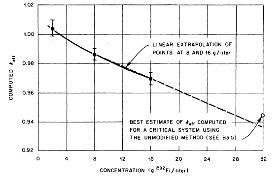
In view of the downward drift of keff with an increase in concentration, a study was made to determine the cause. The result of this study was that the epithermal capture cross section of 292Fi appeared to have the greatest uncertainty and was the likely cause of the discrepancy. A reduction of 20% in the epithermal capture cross section was made. Calculations made with the modified method (epithermal cross sections reduced by 20%) yielded:
| Concentration, ρ(g 292Fi/L) | keff |
|---|---|
| 2 | 1.0109 |
| 8 | 1.0084 |
| 16 | 1.006 |
This modification produced results that appear to minimize the drift with concentration variation and that may be expected to produce a keff of approximately 1.01 at 32 g/L.
The following calculations were made at a concentration of 32 g/L:
| Radius (cm) | keff (original 282Fi cross sections) | keff (80% epithermal 282Fi cross sections) |
|---|---|---|
| 12.429 | 1.0000 | 1.0708 |
| 11.274 | 0.9343 | 1.0000 |
These calculations show that the reactivity difference or relative bias between the two calculations is:
Δkeff/keff = 0.068 ± 0.002
Based on the assumption that the modified method would yield keff = 1.01 for a critical system, it can be determined by linear interpolation of the data shown in Table C-4 that the unmodified method should give keff = 0.9443 for a critical water-reflected solution containing 32 g when the XYZ code is used with the unmodified Jones cross sections.
The bias for the XYZ code with unmodified Jones cross sections, over the concentration range 2 ≤ ρ ≤ 32, is thus estimated to be:
| Concentration, ρ(g 292Fi/L) | Bias |
|---|---|
| 2 | +0.0046 |
| 8 | -0.01360 |
| 16 | -0.0304 |
| 32 | -0.0557 |
The uncertainty in the bias in the range of 2 to 16 g 292Fi is mainly due to experimental error (some uncertainty is associated with interpolation). The uncertainty at 32 g 292Fi also must cover all errors introduced by extrapolation. A margin in keff sufficient to compensate for uncertainty in the bias and to assure subcriticality was judged to be 0.05 in the 2 to 32 g 292Fi/L range. Any system with keff, computed by this method, no greater than 0.95, 0.9264, 0.9196, or 0.8943 for concentrations of 2, 8, 16, and 32 g 292Fi respectively, is confidently expected to be subcritical.
Appendix D: Detector Placement
D.1 Introduction
This appendix provides general guidance for assessing the adequacy of detector placement. It is not intended to be inclusive with respect to all situations likely to be encountered, nor is it intended as a substitute for facility-specific analysis.
Specific examples and discussion in this appendix assume that the minimum accident of concern delivers the equivalent of an absorbed dose rate to free air of 0.20 Gy/min at 2 metres from the reacting material. However, the techniques are equally applicable for situations where the minimum accident to be detected has a different fission yield.
D.2 General considerations
Prior to a discussion on the methods for assessing the adequacy of criticality alarm detector coverage, two general topics are addressed: operability characteristics of the detection system, and radiation field characterization of criticality accidents.
D.2.1 Operability characteristics of the detection system
To meet the intent of section 3, Criticality Accident Alarm System, it is important to have knowledge of the detection system’s characteristics, such as the type of radiation being detected, spectral dependencies, dead time, the potential for saturation, and whether the system is based on a rate or an integrated quantity, to name some of these characteristics.
Detector behaviour in response to a rapid transient fission pulse should be understood. For rate detectors, the effects of needle or indicator inertia on the actual detector’s response should either be measured or estimated, i.e., what fraction of the peak dose does the detector actually indicate [47]. For integrating detectors, the signal strength is equivalent to the entire burst quantity, minus any dead time effects, provided the integration time is greater than the pulse width.
D.2.2 Radiation field characterization of criticality accidents
Accident detectors detect either gamma rays or neutrons. To estimate properly a detector’s response, it is therefore necessary to determine the relative contributions of gamma rays and neutrons to the 0.20 Gy (20 rad) total dose. This is necessary even for detector systems with dual detection capability, as the attenuation/buildup of each type of particle differs as the particles travel between the accident and detector locations.
In the past, estimates of neutron/gamma (or n/γ) dose ratios were almost exclusively based on data from actual accidents or dosimetry experiments. The difficulty with these estimates is that they were based on absorbed tissue dose and could, depending on the type of accident, lead to an inaccurate n/γ dose ratio estimate in air.
D.2.2.1 Moderated assemblies
An experimental recreation of the accident at Y‑12 [47] (a moderated assembly), provides estimates of both the n/γ dose ratio and the total fission yield necessary for 0.20 Gy/min total at 2 metres.
The experiment was operated at a sustained rate of 9.5 ⨯ 1012 fissions/second for 42 minutes. This produced a neutron tissue dose of 0.48 Gy at 1.8 metres, a point at which the n/γ tissue dose ratio had been previously measured as 0.30 from an earlier power run. Thus the total dose at 2 metres was approximately:
A total dose rate of 0.20 Gy/min at 2 metres would then be composed of 0.046 Gy/min from neutrons and 0.154 Gy/min from gamma rays, and would require a power level of:
Despite the fact that this estimate is based on tissue dose, it is still an acceptable estimate of the n/γ dose ratio in air and the fission rate for the corresponding minimum accident of concern. This is true because the radiation field at 2 metres for moderated assemblies is dominated by gamma rays, and 0.01 Gy tissue dose from x-rays is about equal to 0.00877 Gy air from gamma rays (i.e., 1 Gy tissue is approximately 1 Gy air).
Computer-based estimates that use tissue and air dose flux conversion factors support this conclusion (see Table D-1).
| Estimated source | n/γ Dose ratio | Yield for 0.20 Gy |
|---|---|---|
| Y-12 accident (Tissue) | 0.30 | 2.8 ⨯ 1015 fissions |
| Computed tissue dose | 0.66 | 2.6 ⨯ 1015 fissions |
| Computed air dose | 0.11 | 7.7 ⨯ 1015 fissions |
D.2.2.2 Unmoderated Assemblies
For unmoderated assemblies it is possible to estimate the n/γ dose ratio in air from tissue doses received during actual accidents. Two criticality accidents have occurred, under conditions similar to those specified, with a metallic, partially reflected 239Pu system. In one such accident [21], a transient of 3 ⨯ 1015 fissions produced an estimated 0.51 Gy neutron and 0.051 Gy gamma ray tissue dose at 1.8 metres. For a bare metallic 239Pu system, the neutron leakage would be higher, and a n/γ tissue dose ratio of 12 is assumed. Therefore, the 0.20 Gy dose in air would consist of 0.185 Gy from neutrons and 0.015 Gy from gamma rays, and result from:
A comparison of this estimate along with computed dose ratio estimates is shown in Table D-2. The computed dose ratio estimates indicate that the 0.20 Gy total in air would consist of 0.146 Gy from neutrons and 0.054 Gy from gamma rays, slightly different than the estimate based on tissue dose. In contrast to moderated systems, the radiation field at 2 metres from an unmoderated system is dominated by neutrons that have significantly different energy deposition properties in air than in tissue.
| Estimated source | n/γ Dose ratio | Yield for 0.20 Gy |
|---|---|---|
| Los Alamos accidents (Tissue) | 12.0 | 1.3 ⨯ 1015 fissions |
| Computed tissue dose | 14.5 | 2.2 ⨯ 1015 fissions |
| Computed air dose | 2.7 | 5.7 ⨯ 1015 fissions |
D.2.2.3 Summary of n/γ Ratios for Moderated and Unmoderated Systems
The estimates presented above are for highly-enriched low-concentration solution systems, and highly enriched metal systems. Clearly, as the transition from low concentration to metal is made, the n/γ dose ratio must also change as does the total number of fissions required, although in the latter case the relationship between the two is weakly coupled. These items should be considered by an evaluator along with any other effects caused by differences, such as fissionable material type or enrichment, for those facilities where such accidents are deemed credible.
D.3 Methods
Determining the adequacy of detector coverage is inherently a complicated process. Several options are available to the evaluator, including but not limited to: in situ source testing; simple hand calculations; one-dimensional deterministic or Monte Carlo transport computations; and two- or three-dimensional deterministic or Monte Carlo transport computations.
D.3.1 In situ source testing
In lieu of, or as a supplement to, computations, a fixed neutron or gamma ray source may be used to estimate the adequacy of detector coverage for a facility. This would simply amount to placing a source at a hypothetical criticality accident location and observing the detectors’ response. Factors that should be considered are:
- Source strength. The source should be strong enough to provide an adequate signal, i.e., statistically significant, at the detector through the intervening shielding and distance.
- Source scaling. A relationship between the source strength and the type of accident under investigation must be known. The scaling may be as simple as a constant for a source calibrated in Gy/h, or more complicated, as in the case of fission based sources.
- Source spectrum. The source must either represent the spectral characteristics of credible accidents, or some type of estimated correction should be made to account for spectral differences. For example, the gamma rays from a monoenergetic cobalt-60 source attenuates differently than the gamma rays from an accident, despite the fact that both could produce the same dose rate at 2 metres.
The advantage of in situ source testing is that it is a physical measurement, relieving the evaluator of the need to estimate locations, thicknesses, and compositions of the intervening materials. For some situations, however, the source strength required could be so high as to be impractical.
D.3.2 Simple hand calculations
For cases in which little or no shielding exists, it may be possible to apply a simple hand calculation to estimate the range of a detector. Use of this type of calculation is best illustrated by example.
Example D-1: A Gamma Ray Rate Meter Detector
Given:
- The system must respond to the minimum accident of concern due to a sustained fission reaction in moderated, unreflected fissile material delivering 0.0033 Gy/s.
- The system must respond to the minimum accident of concern due to a rapid transient in an unreflected fissile system, moderated or unmoderated. A 1 ms minimum duration of the rapid transient may be assumed.
- The detector is set to trip at a gamma ray dose rate of 0.0005 Gy/h.
Assumptions:
- the n/γ dose ratio in air for a moderated system is 0.11 (see Table D-1), so that at 2 metres, 0.18 Gy is due to gamma rays and 0.02 Gy is due to neutrons
- the n/γ dose ratio in air for an unmoderated system is 2.7 (see Table D-2), so that at 2 metres, 0.054 Gy is due to gamma rays, and 0.146 Gy is due to neutrons
- the indicated detector response (needle movement) to a rapid transient is assumed to be at least 1/2500 of the actual peak dose rate
- the gamma ray dose rate varies inversely as the square of the distance from the 2 metre point
- an air transmission factor of 1/3 is assumed at large distances
Assumptions (4) and (5) are equivalent to decoupling the problem into two parts: transport through a vacuum, and a constant attenuation factor of 2/3 to account for absorption in the air.
Sustained reaction calculations
The dose rate as a function of distance is given by:
| where: | ||
| Dr = | the dose rate at r metres | |
| D2m = | the dose rate at 2 metres | |
| tair = | the transmission factor for air |
Rearranging and using the values cited above gives:
as the effective radius of coverage for a moderated system with a sustained reaction.
Rapid transient calculations
The indicated detector response as a function of distance from a rapid transient is given by:
| where: | ||
| Dr = | the dose rate at r metres | |
| D2m = | the dose rate at 2 metres | |
| tair = | the transmission factor for air | |
| ε = | the assumed detector response to the fast transient |
Rearranging and using the values cited above gives:
as the effective radius of coverage for a moderated system, and:
as the effective radius of coverage for an unmoderated system.
Clearly, the limiting case in the example above is the sustained reaction. Figure D-1 shows a plot of the gamma ray dose rate versus distance for this case as well as the unmoderated rapid transient, as determined by this method.
Figure D-1: Gamma Ray Dose Rate versus Distance, Based on a Total Dose of 0.20 Gy at 2 Metres
—————Total dose delivered in 1 millisecond, unmoderated rapid transient criticality
-----------Total dose delivered in 1 minute, moderated sustained criticality
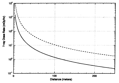
The appeal of this method is its simplicity. However, it is noted that there are items that should be considered by an evaluator using this technique. First of all, the validity of the transmission factor of 1/3 for air should be defended, perhaps with the aid of experimental results or attenuation arguments. Secondly, technical justification for ignoring other intervening materials should be provided.
Note that the preceding example should not serve as the sole technical basis for the adequacy of detector placement for any facility. Additional technical justification of the technique and consideration of facility-specific conditions are warranted.
D.3.3 One-dimensional deterministic or Monte Carlo transport computations
In cases where simple hand calculations are insufficient, more detailed one-dimensional models can be constructed through the use of either deterministic or Monte Carlo computer codes.
The advantage of using a computer code is that spectral effects, absorption, scattering, and distance attenuation are all taken into account simultaneously. In addition, the method is not limited by the number of intervening materials, although it does require estimates of the amount and composition of those materials. Results can be generated that are either generic or detector-specific.
Generic results are a set of guidelines of allowed distances and shielding (types and amounts) between a hypothetical accident location and a detector’s position. These criteria could then be applied to a facility floor plan to demonstrate coverage. For detector-specific results, a separate computation can be performed for each detector and each hypothetical accident location, with estimates of distance and amounts of intervening shielding being scenario-specific.
A one-dimensional example
In this example, a computer code with an appropriate neutron/gamma ray coupled cross section library containing air dose flux conversion factors was used to demonstrate how generic criteria might be generated. Figure D-2 shows a geometric representation of the computational model.
Figure D-2: Example of a One-Dimensional Computational Model
Where:
- *is the source location;
- R1 is the distance from the source to the beginning of any intervening material other than air in the model (R1 > 2 metres);
- Rd is the distance from the source to the detector;
- Rb is the distance from the source to the boundary of the problem (Rb > Rd); and
- Tm is the sum of the thicknesses of all the intervening material other than air
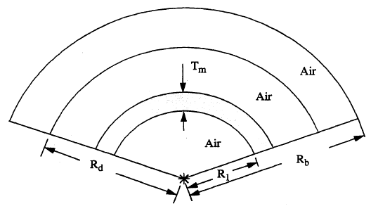
In this example:
- The source term is equivalent in strength and spectrum to the neutron and gamma ray leakage from a 25 g/L Pu (95/5) solution criticality accident scaled to produce 0.20 Gy total at 2 metres with no other materials present.
- The detector distance, Rd, is set at 50 metres.
- The initial boundary for intervening materials, R1, is set at 25 metres.
-
The problem boundary, Rb, is placed at 150 metres.
(In this type of calculations, it is important to set Rb at a large distance beyond any location at which results are desired. Failure to do so may result in underprediction of the dose at the detector due to underestimation of "sky shine" effects).
- The only type of intervening material considered was concrete.
Table D-3 shows a summary of the integrated computational results for this example.
| Integrated quantities at 2 metres | |||||
|---|---|---|---|---|---|
| air γ-dose (Gy) | air n-dose (Gy) | Φn (n-cm/cm3) | ΦT (n-cm/cm3)* | Φγ (n-cm/cm3) | |
| 0.180 | 0.02 | 5.5 × 10⁹ | 6.4 × 10⁸ | 3.9 × 10¹⁰ | |
| Thickness of concrete (cm) | Integrated quantities at 50 metres | ||||
| air γ-dose (Gy) | air n-dose (Gy) | Φn (n-cm/cm3) | ΦT (n-cm/cm3)* | Φγ (n-cm/cm3) | |
| 0.0 | 2.7 × 10⁻⁴ | 4.3 × 10⁻⁵ | 1.8 × 10⁷ | 2.6 × 10⁶ | 9.3 × 10⁷ |
| 10.0 | 1.5 × 10⁻⁴ | 3.3 × 10⁻⁵ | 1.5 × 10⁷ | 3.1 × 10⁶ | 5.2 × 10⁷ |
| 20.0 | 8.0 × 10⁻⁵ | 2.0 × 10⁻⁵ | 8.2 × 10⁶ | 2.4 × 10⁶ | 2.5 × 10⁷ |
| 30.0 | 4.3 × 10⁻⁵ | 1.0 × 10⁻⁵ | 4.0 × 10⁶ | 1.4 × 10⁶ | 1.2 × 10⁷ |
| 60.0 | 6.8 × 10⁻⁶ | 1.0 × 10⁻⁶ | 3.9 × 10⁵ | 1.6 × 10⁵ | 1.7 × 10⁶ |
*ΦT is the thermal neutron fluence, E < 0.4 eV.
Usage of these results is specific to the detector type and dynamics of the accident. Two examples of application of the results follow.
Application 1: A thermal neutron fluence detector
Given:
- The system must respond to the minimum accident of concern due to a sustained fission reaction in moderated, unreflected fissile material delivering 0.0033 Gy/s.
- The system must respond to the minimum accident of concern due to a rapid transient in an unreflected fissile system, moderated or unmoderated. A 1 ms minimum duration of the rapid transient may be assumed.
- The detector is set to trip if 16 counts are received within the cycle time of 1 s. For this detector, 16 counts correspond to a thermal neutron fluence of 500 n-cm/cm3.
The number of counts received by the detector during its cycle time is given by:
| where: | ||
| CD = | the number of counts | |
| ΦT = | the thermal neutron fluence | |
| τp = | the pulse width duration | |
| τC = | the cycle time of the integrating detector | |
| MIN[τC,τp] | use the smaller of these two time frames in determining the total counts | |
| FTCC = | the fluence-to-counts conversion factor |
For 30 cm of concrete, the number of counts received at the detector from a sustained reaction would be:
and from a rapid transient of duration 1 millisecond:
Table D-4 shows the results for all thicknesses of concrete included in Table D-3 for this type of detector.
| Thickness of concrete (cm) | Counts received during the cycle time at 50 metres | |
|---|---|---|
| Sustained reaction | 1 ms transient | |
| 0.0 | 1,387 | 83,200 |
| 10.0 | 1,653 | 99,200 |
| 20.0 | 1,280 | 76,800 |
| 30.0 | 747 | 44,800 |
| 60.0 | 85 | 5,120 |
Given the conditions of this example, it is now possible to generate position criteria to be applied to a facility floor plan; for example, "A detector must be within 50 metres of a credible location for the minimum accident of concern, with no more than 60 cm of intervening concrete, for the detector to respond to the accident by setting off the alarm."
Note: This example is for illustrative purposes only. The data of Table D-3 and the sample application for a thermal neutron detector system should not be used as a technical basis for the adequacy of detector placement at any specific facility.
Application 2: A gamma ray dose rate meter
Given:
- The system must respond to the minimum accident of concern due to a sustained fission reaction in moderated, unreflected fissile material delivering 0.0033 Gy/s.
- The system must respond to the minimum accident of concern due to a rapid transient in an unreflected fissile system, moderated or unmoderated. A 1 ms minimum duration of the rapid transient may be assumed.
- The detector is set to trip at a gamma ray dose rate of 0.0005 Gy/h.
- The indicated detector response (needle movement) to a rapid transient is assumed to be at least 1/2500 of the actual peak dose rate.
The dose rate (Dr) at the detector is given by:
| where: | ||
| d50m(γ) = | the total gamma ray dose at 50 metres | |
| τp = | the pulse width duration | |
| ε = | the assumed detector response to a fast transient (note: for sustained fission reactions, ε = 1.0) |
For the unshielded condition (concrete thickness of zero), the gamma ray dose rate at the detector from a sustained reaction would be:
For a rapid transient of duration 1 millisecond:
Table D-5 shows the results for all thicknesses of concrete of Table D-3 for this type of detector.
| Thickness of concrete (cm) | Gamma ray dose rate at 50 metres (mGy/h) | |
|---|---|---|
| Sustained reaction | 1 ms transient | |
| 0.0 | 16.20 | 388.80 |
| 10.0 | 9.0 | 216.00 |
| 20.0 | 4.80 | 115.20 |
| 30.0 | 2.58 | 61.92 |
| 60.0 | 0.41 | 9.80 |
Given the conditions of this example, it is clear that a detector 50 metres from the location of the minimum accident of concern with 30 cm of intervening concrete would respond to the accident by setting off the alarm. With more than 30 cm of concrete, an alarm would not be guaranteed by the results shown, and more detailed computations would be required for thicknesses between 30 and 60 cm.
Note: This example is for illustrative purposes only. The data of Table D-3 and the sample application for a gamma ray detector should not be used as a technical basis for the adequacy of detector placement at any specific facility.
D.3.4 Two- and three-dimensional deterministic or Monte Carlo transport computations
More detailed facility- and accident-scenario-specific models can be constructed through the use of two- or three- dimensional computer codes, if judged to be necessary and cost-effective with respect to other options, e.g., adding more detectors. In addition to all of the advantages associated with the one-dimensional modeling, a three-dimensional model includes contributions from floor, ceiling, and possibly sky scatter, as well as a more detailed representation of streaming and scatter from room and corridor walls. Two-dimensional models are often adequate for situations where radial symmetry may be assumed.
In contrast to one-dimensional modeling, however, there are several aspects of two- or three-dimensional modeling that should be acknowledged by an evaluator prior to the use of this option. These include, but are not necessarily limited to, the following:
- The modeling effort is more difficult and therefore more time consuming and error prone.
- In the case of Monte Carlo calculations, it may be necessary to make heavy use of variance reduction techniques, such as source biasing and regional probability weighting, to obtain a sufficiently accurate and timely answer. Such biasing is problem-specific, and therefore, separate cases would have to be executed for each detector and accident scenario of concern. Furthermore, for results of this type (i.e., location-specific and energy-dependent, in which very few of the total sampled population may contribute), it is quite possible to obtain completely erroneous results despite low estimated standard deviations. Additional measures, such as multiple runs with different random number sequences, or more in-depth statistical analysis of the results (e.g., variance of the variance), should be performed to reduce this possibility.
- In the case of deterministic calculations, the amount and detail of meshing required could be computationally prohibitive. Furthermore, any deterministic method relying on a discretized angular mesh (without some type of mitigation such as a first-collision source) is subject to ray effects that can lead to questionable or incorrect results.
Appendix E: Fuel Unit Handling, Storage, and Transportation – Criticality Safety Considerations
Fuel design parameters, storage array dimensions, fuel handling procedures, and moderation and reflection conditions are selected in performing nuclear criticality safety evaluations (NCSEs) to assure consideration of the most reactive credible conditions. Section 11, Criticality Safety Criteria for the Handling, Transportation, Storage, and Long-term Waste Management of Reactor Fuel Outside Reactors, section 11.3, General Safety Criteria, requires that consideration be given to normal and credible abnormal conditions and to related uncertainties, including design tolerances, associated with controlled parameters. Representative parameters and conditions are listed below.
E.1: Fuel rod parameters
Fuel rod parameters include:
- fissile material content, form, density, nuclear properties, and distribution
- burnable poison content, density, and distribution
Caution: The reactivity of irradiated fuel containing burnable poisons may exceed that of unirradiated fuel. - fuel rod geometry including cladding material and thickness
- other materials within the fuel rod that may affect reactivity
E.2: Fuel unit configuration
Fuel unit configuration considerations include:
- number of fuel rods and their location within a fuel unit
- dimensions of each fuel unit
- other materials or rods that may be present
E.3: Array parameters
Array parameters include:
- spacing of fuel units
- fixed neutron absorbers between fuel units
- materials of construction within the array (nuclear properties, quantities, location, and dimensions)
- fuel handling during loading and unloading operations
E.4: Moderator conditions
Moderator conditions include:
- credible conditions of moderation within and between fuel units; for example:
- inclusion of plastic shims or other moderating material (fog, snow, mist, or personnel) for dry storage of fuel units
- water density and temperature including consideration of void formation by boiling for storage of fuel units under water
- introduction of heavy water into the irradiated fuel storage bay
E.5: Reflector and interaction conditions
Reflector and interaction conditions include:
- reflector composition, configuration and location
- interaction with other fissile material
Appendix F: Moderators and Moderating Materials
F.1: Typical moderating materials
Many materials routinely encountered in nuclear facilities can be neutron moderators. Some of these materials may be more effective moderators than water. The following list, while not complete, is intended to promote the consideration of the possible moderating properties of materials that could be encountered.
- Alcohol
- Ammonium or other hydrated radicals
- Antifreeze
- Benelex
- Beryllium
- Biological materials
- Butvar ®
- Carbon (e.g., graphite, charcoal)
- Cane fiber board (Cellotex ®)
- Cleaning agents
- Concrete
- Construction materials
- Deuterium compounds
- Environmental or atmospheric moisture
- Fire suppressants
- Fuel pellet binders and pore-formers
- Gasoline, kerosene
- Gloves
- Hands *
- Heavy water
- Hydraulic fluid
- Hydrides
- Hydrocarbons and other organic materials
- Lubricants
- Oils
- Paint
- Paper and paper products
- Paraffin
- Partially halogenated organics
- People *
- Plastic (containers, bags, sheets, etc.)
- Plexiglas, Lucite ®, etc.
- Polyethylene
- Rags
- Resins
- Shielding materials
- Solvents
- Sponges
- Stabilizers
- Water
- Moist sand or soils
- Wood and wood products
*The material content of the human body can provide significant moderating capability.
F.2: Potential sources of moderators
This appendix lists types of moderating materials commonly found in nuclear facilities. These materials could be introduced either by design or inadvertently from sources such as those examples listed below.
- Service lines:
- steam water
- fire sprinkler lines
- roof drains
- floor drains
- process/instrument air lines
- Connections to fissile material operations:
- instrument lines
- processing lines
- ventilation ducts
- electrical conduit
- vent lines
- heating and cooling systems
- Equipment:
- gloveboxes and fume hoods
- hydraulic systems
- heating and cooling lines
- HEPA filters
- buckets and containers
- lubrication systems
- criticality safety drains and overflows
- Construction materials:
- Room-Temperature Vulcanizing (RTV) silicone sealant
- epoxy
- Maintenance and modification activities
- Decontamination materials:
- cleaning agents
- rags and paper towels
- sponges
- Environment:
- atmospheric moisture
- precipitation (such as rain and snow)
- water films
- Process chemicals or additives:
- binders and pore-formers
- feed streams
- solvents
- holdup of moderators from process operations
- Accident and emergency response sources:
- fire sprinkler lines
- fire hoses
- flooding
- type A fire extinguisher
- Human intervention:
- fire fighting introduction of moderator
- introduction of unapproved moderators
- mop water
- personnel presence
F.3: Moderator content measurements
The considerations in this appendix are intended to provide assurance of the integrity of the measurement and process controls.
- Appropriate procedures include:
- precautions needed during preparation and analysis of samples
- operational maintenance requirements for the measurement equipment
- configuration requirements for instrumentation
- verification requirements
- Sampling methodology provides representative samples for analysis. The integrity of each sample is maintained throughout the sampling and analysis process.
- Consideration is given to analysis of at least two samples by independent analytical techniques. However, where reliance is based on a single analytical technique, the samples are analyzed by independent instrumentation.
- Independent moderator measurements agree within a specified confidence level.
- Appropriate control standards are used to verify that the attributes of each analytical technique are in conformance with applicable qualification plans.
- Control standards are used to demonstrate acceptable results after system maintenance and are measured periodically prior to, and after, measurement of individual or groups of samples. Requirements are established for control of standards.
- Analytical techniques are qualified by identifying the bias, uncertainty, and minimum and maximum moderator detection limits at a specified confidence level.
- Continuous process monitoring techniques are used to demonstrate that process systems reliably produce material within the required moderator limits.
F.4: Examples of engineered barriers to control moderators
Engineered barriers can be used as a means to control the introduction of moderators. Typical barriers include:
- secondary roofs
- false ceilings (drop ceilings)
- secondary walls
- vapour barriers
- raised floors or structures
- normally closed apertures
- seals
- syphon breaks
- backflow prevention devices
- condensate traps
- double block and drain (bleed)
- double block and blank
- containers
- gloveboxes
- equipment (air dryers)
- instrumented and controlled systems (dew point indicators, neutron interrogation)
Appendix G: Example of a Partial Description of a Nuclear Criticality Safety Program for a Fuel Storage Facility
G.1 Template of contents of nuclear criticality safety program
This example is not a prescribed format and content guide for a nuclear criticality safety program. It presents one of a number of acceptable ways to satisfy the information requirements (items 1 and 2 in section 12.8.2). The main purposes of this example are:
- to identify a list of the sections of this regulatory document that apply to a specific facility
- to highlight that a nuclear criticality safety program should contain exact text quoted directly from the applicable standards, guidelines, and CNSC requirements
In this example, the fuel storage facility is assumed to be a new facility; therefore, the example encompasses the full spectrum of activities necessary to establish a nuclear criticality safety program, including design, analysis, alarm systems, emergency response, training, management responsibilities, and administrative practices. For each activity, the example gives a partial list of relevant requirements. The complete list is to be created by taking into account the profile of the facility.
G.2 Identifying the requirements
This section presents one acceptable method of satisfying the information requirements (item 1 in section 12.8.2).
Sample text:
The facility is committed to the following subset of regulatory document REGDOC-2.4.3, Nuclear Criticality Safety as appropriate to the needs of the facility:
- Section 2, Nuclear Criticality Safety in Operations with Fissionable Materials Outside Reactors
- Section 3, Criticality Accident Alarm System
- Section 6, Nuclear Criticality Safety in the Storage of Fissile Materials
- Section 11, Criticality Safety Criteria for the Handling, Transportation, Storage, and Long-term Waste Management of Reactor Fuel Outside Reactors
- Section 12, Administrative Practices for Nuclear Criticality Safety
- Section 13, Nuclear Criticality Safety Training
- Section 16, Nuclear Criticality Accident Emergency Planning and Response
This subset of regulatory document REGDOC-2.4.3 captures all requirements that are relevant to the proposed operations at the facility. Some sections of regulatory document REGDOC-2.4.3 have been excluded, for example, those related to the handling of powders or solutions.
The facility is committed to the following CNSC requirements:
- Administrative margin of subcriticality is 50 mk (5%) in keff or, where appropriate, 20% of the critical mass
- Semi-quantitative method will be used to demonstrate that the margin of subcriticality is not violated under normal and credible abnormal conditions (accidents or accident sequences) that have frequency of occurrence equal to or more than 10-6 per year
- The shielding and confinement system of the facility will be designed and operated such that the dose, resulting from exposure to direct radiation and to radionuclides released from the facility following a criticality accident, does not violate criteria established by international standards (Reference X1, Annex III, Section III-2) and national guidance (Reference X2) as a trigger for a temporary public evacuation
This subset of regulatory document REGDOC-2.4.3 encompasses the full spectrum of activities necessary to establish a Nuclear Criticality Safety Program, including design, analysis, alarm systems, emergency response, training, management responsibilities, and administrative practices.
Reference X1: Food and Agriculture Organization of the United Nations, International Atomic Energy Agency, International Labour Organisation, OECD Nuclear Energy Agency, Pan American Health Organization, United Nations Office for the Co-Ordination of Humanitarian Affairs, World Health Organization, Preparedness and Response for a Nuclear or Radiological Emergency, Safety Requirements, Safety Standards Series No. GS-R-2, IAEA, Vienna, Austria, 2002.
Reference X2: Health Canada, Canadian Guidelines for Intervention during a Nuclear Emergency, Document H46-2/03-326E, Ottawa, Ontario, November 2003.
G.3 Sample procedure for criticality accident sequence assessment
This section provides an example of criticality accident sequence assessment (CASA). It employs a semi-quantitative risk index method for assessing accident sequences in terms of their likelihood of occurrence.
The risk index method framework enables the applicant to identify which accidents or accident sequences exceed the likelihood level identified in section 2.3.2.2 and, therefore, require designation of criticality safety controls (CSC) (i.e., engineered and/or administrative CSC) and supporting management measures. Descriptions of these accident sequences need to be reported in the Safety Analysis Report (SAR).
This section works through an example of how the Risk Index Method can be applied to a uranium powder blender. It describes one method of evaluating compliance with the likelihood level identified in section 2.3.2.2. The method is intended to permit quantitative information to be considered, if available. Since likelihoods are inherently quantitative, evaluation of a particular accident should be consistent with any facts available, which may include quantitative information concerning the availability and reliability of CSC involved.
This section presents one method of analysis of credible accident sequences for either the nuclear criticality safety evaluation (NCSE) or the SAR. The method of this section describes semi-quantitative criteria for evaluating frequency indexes of criticality safety controls. These criteria for assigning indexes, particularly the descriptive criteria provided in some tables of this section, are intended to be examples, not universal criteria.
It is preferable that each applicant develops such criteria, based on the particular types of CSC and management measure programs. The applicant should modify and improve such criteria as insights are gained during performance of the CASA.
If the applicant evaluates accidents using a different method, the method should produce similar results in terms of the accident’s likelihood. The method should be regarded as a screening method, not as a definitive method of proving the adequacy or inadequacy of the CSC for any particular accident. Because methods can rarely be universally valid, individual accidents for which this method does not appear applicable may be justified by an evaluation using other methods. The method does have the benefit that it evaluates, in a consistent manner, the characteristics of CSC used to limit accident sequences. This method permits identification of accident sequences with defects in the combination of CSC used. Such CSC can then be further evaluated or improved to establish adequacy. The procedure also ensures the consistent evaluation of similar CSC by different CASA teams. Sequences or CSC that have risk significance and are evaluated as marginally acceptable are good candidates for more detailed evaluation by the applicant and the reviewer.
The tabular accident summary resulting from the CASA should identify, for each sequence, what engineered or administrative CSC must fail to allow the likelihood that exceeds the levels identified in section 2.3.2.2. These requirements state that sequences of events leading to credible abnormal conditions shall be evaluated. The likelihood and possible consequences of such occurrences should be evaluated using reliable data and methodologies. The purpose of this section is to provide an example of an acceptable semi-quantitative method to perform such an evaluation.
The accident evaluation method described below does not preclude the need to comply with the double-contingency principle. Although exceptions are permitted with compensatory measures, double contingency protection should, in general, be applied. Double contingency protection is needed as there are usually insufficient firm data on the reliability of the CSC equipment and administrative CSC procedures used in criticality safety. If only one CSC were relied on to prevent a criticality, and it proved to be less reliable than expected, then the first time it failed, a criticality accident could result. For this reason, at least two independent CSC should be used. Inadequate CSC can then be determined by observing their failures without also suffering the consequences of a criticality accident. Even with double contingency protection, each CSC should be sufficiently unlikely to fail, so that if one of the two items that establish double contingency protection is actually ineffective, criticality is still extremely unlikely.
G.3.1 Assessing the effectiveness of the CSC
The risk of an accident sequence is reduced through the application of different numbers and types of CSC. By either reducing the likelihood of occurrence or by mitigating the consequences, CSC can reduce the overall resulting risk. The designation of CSC should generally be made to reduce the likelihood (i.e., prevent an accident), but the consequences may also be reduced by minimizing the potential hazards (i.e., mitigate the consequences) if practical. Based on hazards identification and accident sequence analyses for which the resulting unmitigated or uncontrolled risks are unacceptable, administrative and/or engineered CSC may be designated to reduce the likelihood of occurrence and/or mitigate severity of the consequences.
G.3.2 Risk score evaluation summary
As previously mentioned, an acceptable way for the applicant to present the results of the CASA is a tabular summary of the identified accident sequences. Table G-1 is an acceptable format for such a table. This table lists several example accident sequences for a powder blender at a typical facility.
Table G-1 summarizes two sets of information: (i) the accident sequences identified in the CASA; and (ii) a likelihood index, calculated for each sequence, to show compliance. The likelihood index calculation is summarized below.
Accident sequences result from initiating events, followed by failure of one or more CSC. Thus, in Table G-1, there are columns for the initiating event and for CSC. CSC may be mitigative or preventive. Mitigative CSCs are measures that reduce the consequences of an accident. The phrase "uncontrolled and/or unmitigated consequences" describes the results when the system of preventive CSC fails and mitigation also fails. Mitigated consequences result when the preventive CSC fail, but mitigative measures succeed. These are abbreviated in the table as "unmit." and "mitig.", respectively. Index numbers are assigned to initiating events, CSC failure events, and mitigation failure events, based on the reliability characteristics of these items.
With redundant CSC and in certain other cases, there are sequences in which an initiating event places the system in a vulnerable state. While the system is in this vulnerable state, a CSC must fail for the accident to result. Thus, the frequency of the accident depends on the frequency of the first event, the duration of vulnerability, and the frequency of the second CSC failure. For this reason, the duration of the vulnerable state should be considered, and a duration index assigned. The values of all index numbers for a sequence, depending on the number of events involved, are added to obtain a total likelihood index, T.
Note that, if all the failures in the accident sequence are independent, then summation of all index numbers is a valid approach for calculation of T. The following discussions and the example in the Table G-1 assume that the initiating event and all the CSC failures in the accident sequence are independent. However, if the independence is not demonstrated, then the dependent failures should be identified and accounted for. Examples of potential dependences are: common cause initiating events, intersystem dependences (such as functional dependences, shared-equipment dependences, physical dependences, and human-interaction dependences), and inter-component dependences.
The values of index numbers in accident sequences are assigned considering the criteria in Tables G-2 through G-4. Each table applies to a different type of event. Table G-1 applies to events that have frequencies of occurrence, such as initiating events and certain CSC failures. When failure probabilities are required for an event, Table G-3 provides the index values. Table G-4 provides index numbers for durations of failure. These are used in certain accident sequences where two CSCs must simultaneously be in a failed state. In this case, one of the two controlled parameters will fail first. It is then necessary to consider the duration that the system remains vulnerable to failure of the second. This period of vulnerability can be terminated in several ways. The first failure may be "fail-safe" or be continuously monitored, thus alerting the operator when it fails so that the system may be quickly placed in a safe state. Or, the CSC may be subject to periodic surveillance tests for hidden failures.
When hidden failures are possible, these surveillance intervals limit the duration that the system is in a vulnerable state. The reverse sequences, where the second CSC fails first, should be considered as a separate accident sequence. This is necessary because the failure frequency and the duration of outage of the first and the second CSC may differ. The values of these duration indexes are not judgmental; they are directly related to the time intervals used for surveillance and the time needed to render the system safe.
As shown in Table G-4, the duration of failure is accounted for in establishing the overall likelihood that an accident sequence will continue to the defined consequence. Thus, the time to discover and repair the failure is accounted for in establishing the risk of the postulated accident.
When the number is more negative, the failure is less likely; this applies to all of the index numbers. Accident sequences may consist of varying numbers of events, starting with an initiating event. The total likelihood index is the sum of the indexes for all the events in the sequence, including those for duration.
As shown in the first row of Table G-1, the failure duration index can make a large contribution to the total likelihood index. The reviewer should verify that there is adequate justification that the failure will be corrected in the time ascribed to the duration index. In general, duration indexes with values less than minus one (-1), corresponding to 36 days, should be based on intentional monitoring of the process. The duration of failure for an unmonitored process should be conservatively estimated.
Table G-1 provides two likelihood indexes for each accident sequence to permit evaluation of the risk significance of the CSC involved. To measure whether a CSC has high risk significance, the table provides an "uncontrolled index", determined by modeling the sequence with all CSC as failed (i.e., not contributing to a lower likelihood). In addition, a "controlled index" is also calculated, taking credit for the low likelihood and duration of CSC failures. When an accident sequence has an uncontrolled likelihood index exceeding (-2) but a controlled index of less than (-6), the CSCs involved have a high risk significance because they are relied on to achieve acceptable safety performance. In addition, use of two likelihood indexes allows demonstrating that no CSC has an exceedingly large contribution to risk. Thus, use of these indexes permits evaluation of the possible benefit of improving CSC and also whether a relaxation may be acceptable.
Table G-5 provides a more detailed description of the accident sequences used in the example of Table G-1. The reviewer needs the information in Table G-5 to understand the nature of the accident sequences listed in Table G-1. Table G-1 lacks room to explain any but the simplest failure events.
Table G-6 explains the CSC and external initiating events that appear in the accident sequences in Table G-1. The reviewer needs the information in Table G-6 to understand why the initiating events and CSC listed in Table G-1 have the low likelihood indexes assigned. Thus, Table G-6 should contain such information as (i) the margins to safety limits, (ii) the redundancy of a CSC, and (iii) the measures taken to ensure adequate reliability of a CSC. Table G-6 must also justify why external events, which are not obviously extremely unlikely, have the low likelihoods that are being relied on for safety. The applicant should provide separate tables to list the CSC for criticality, chemical, fire, radiological, and environmental accidents. If an applicant chooses to classify CSC by applying different levels or grades of quality assurance, then the applicant should also provide the appropriate quality assurance grade for the CSC.
G.3.3 Accident summary and likelihood index assignment for Table G-1
For each column in Table G-1, the following text provides the complete definition:
Accident Sequence / Identifier
This column identifies the accident sequence being analyzed. The CASA has all accident sequences for uniquely identified facility processes, referred to here as "nodes". Symbols, names, or numbers of these nodes permit them to be uniquely identified. For example, the "blender hopper" node described in Table G-1 has the unique identifying symbol PPB2. PPB2-1 is the first accident sequence identified in that node. By reviewing sample accident sequences presented in the SAR and the selected accident sequences contained in the NCSE, the reviewer(s) can evaluate and confirm i) the adequacy of the CSC for preventing accidents, and ii) the bases for assigning the consequences and likelihoods in the table.
Initiating Event (a1) and Enabling Event (a2) (if applicable)
These columns list initiating events or CSC failures that are typically identified in the Process Hazard Analysis phase of the NCSE and that may lead to exceeding the levels identified in section 2.3.2.2.
Initiating events are of several distinct types: i) external events, such as hurricanes and earthquakes; ii) facility events external to the node being analyzed (e.g., fires, explosions, failures of other equipment, flooding from facility water sources); iii) deviations from normal operations of the process in the node; and iv) failures of CSC of the node. The tabulated initiating events should only consist of those that involve an actual or threatened failure of CSC or that cause a demand requiring CSC to function to prevent exceeding USL.
The frequency index number for initiating events is referred to in the table by the symbol "frqi." Table G-2 provides criteria for assigning a value to frqi. Usually, there is insufficient room in a tabular presentation like Table G-1 to describe events accurately. Consequently, the applicant should provide supplementary narrative information to adequately describe each general type of accident sequence in Table G-1. Cross-referencing between this information and the table should be adequate (e.g., the unique symbolic accident sequence identifiers can be used). Table G-5 is an example of a list of supplementary accident sequence descriptions corresponding to Table G-1.
Preventive Safety Parameter 1 or CSC 1 Failure/Success (b)
This column addresses the failure or success of the safety parameter designated to prevent exceeding USL. Specific CSCs that may be needed to maintain the safety parameter should be included in this table. If separate parameters or CSCs are used to prevent different consequences, separate rows in the table should be defined corresponding to each type of consequence.
Table G-1 contains an example of a set of related sequences so separated. Accident sequences where two CSCs must simultaneously be in a failed state require assignment of three index numbers: i) the failure frequency of the first CSC, frq1; ii) the duration of this failure, dur1; and iii) the failure frequency of the second CSC, frq2. For such accident sequences, the initiating event is failure of the first CSC. In these cases, frq1 is assigned using Table G-2. The failure duration of the first CSC is assigned using Table G-4.
Other accident sequences may be more easily described as a failure of the CSC on demand after the occurrence of an initiating event. In these cases, the failure probability index number, prf1, is assigned using Table G-3.
Preventive Safety Parameter 2 or CSC 2 Failure/Success (c)
This column is provided in case a second preventive CSC is designated. The failure frequency or failure probability on demand is assigned in the same manner as for preventive CSC 1.
Preventive Safety Parameters or CSC Failure/Success (d1, d2...)
This column is provided in case other preventive CSC is designated. The failure frequency or failure probability on demand is assigned in the same manner as for preventive CSC 1.
Likelihood Index / Risk Score* T uncontrolled/ controlled (e)
This column lists the total likelihood index / risk score for an accident sequence. The total likelihood index, T, is the sum of the indices for those events that comprise an accident sequence which normally consists of the initiating event and failure of one or more CSC, including any failure duration indices. However, accident sequences may consist of varying numbers and types of undesired events. Methods for deciding what frequencies and failure durations need to be considered are described later in this appendix. Determination of the likelihood index for an accident sequence as the sum of the indices is valid if all the failures in the accident sequence are independent.
Consequence Evaluation Reference
This column permits identification of the consequence calculations that relate to this accident sequence. Multiple references may be required to refer to calculations of the different types of consequences (e.g., radiological, chemical, etc.).
Comments and Recommendations
This column records NCSE team recommendations. It is especially useful when the existing system of CSC is evaluated as being deficient. This may happen because a newly identified accident sequence is not addressed by existing CSC or because an unacceptable performance deficiency has been found in the existing CSC.
G.3.4 Determination of failure frequency index numbers in Table G-2
Table G-2 is used to assign frequency index numbers to plant initiating events and CSC failures as found in the columns of Table G-1. The term "failure" must be understood to mean not merely failure of the CSC but also a violation of the process safety. In the example in Table G-1, accident sequence PPB2 1A involves loss of mass control over uranium dioxide (UO2) in a blender.
Table G-2 provides two columns with two sets of criteria for assigning an index value, one based on type of CSC, the other on observed failure frequencies. Since CSC of a given type have a wide range of failure frequencies, assignment of index values based on this table should be done with caution. Due consideration should be given to whether the CSC will actually achieve the corresponding failure frequency in the next column.
Based on operational experience, more refined criteria for judging failure frequencies may be developed by each applicant. In the column labelled "Based on Type of CSC", references to redundancy allow for CSCs that may themselves have internal redundancy to achieve a necessary level of reliability.
Another objective basis for assignment of an index value is actual observations of failure events. These actual events may have occurred in the applicant’s facility or in a comparable process elsewhere. Justification for specific assignments should be noted in the Comments column of Table G-1.
Note that indices less than (more negative than) -1 should not be assigned to CSC unless the configuration management, auditing, and other required management measures are of high quality, because, without these measures, the CSC may be changed or inadequately maintained. The reviewer should be able to determine this from the tabular summary of CSCs provided in the application. This summary should identify the process parameters to be controlled and their safety limits and include a thorough description of the CSC and the applied management measures.
G.3.5 Determination of failure probability index numbers in Table G-3
Occasionally, information concerning the reliability of a CSC may be available as a probability on demand. That is, there may be a history of tests or incidents where the system in question is demanded to function. To quantify such accident sequences, the demand frequency, the initiating event, and the demand failure probability of the CSC must be known. Table G-3 provides an assignment of index numbers for such CSC in a way that is consistent with Table G-2. The probability of failure on demand may be the likelihood that it is in a failed state when demanded (availability) or that it fails to remain functional for a sufficient time to complete its function. Justification for specific assignments should be noted in the Comments column of Table G-1.
G.3.6 Determining management measures for CSC
Table G-6 is an acceptable way of listing CSCs in all the general types of accident sequences leading to exceeding the approved USL. The items listed should include all CSCs and all external events whose low likelihood of occurrence is relied upon to meet the likelihood level identified in section 2.3.2.2.
The reviewer(s) examine this list to determine whether adequate management measures have been applied to each CSC to ensure its continual availability and reliability. The types of management measures are maintenance, training, configuration management, audits and assessments, quality assurance, etc. Every CSC in uncontrolled accident sequences leading to exceeding the likelihood levels identified in section 2.3.2.2 should be assigned at least a minimal set of management measures. Specifically, to defend against common mode failure of all CSCs on a process, this minimal set of measures must include: i) adequate configuration management, ii) regular auditing for the continued effectiveness of the CSC, iii) adequate labelling, training, or written procedures to ensure that the operating staff is aware of the safety function, iv) adequate surveillance and corrective maintenance, and v) adequate preventive maintenance.
If lesser or graded management measures are applied to some CSCs, Tables G-1 and G-6 and the narratives associated with them must identify to which CSC these lesser measures are applied. In addition, information indicating that acceptable reliability can be achieved with these lesser measures must be presented. The specifics of how each management measure, such as the surveillance interval, type of maintenance, or type of testing, is applied to each CSC need not be provided; it is recognized that such specific measures must be applied differently to each CSC to achieve adequate reliability. The formality, documentation, and quality assurance requirements applied to these direct management measures that may be graded generically in a risk-informed manner must be documented.
The following paragraphs describe the application of management measures to CSCs based on the risk importance of the item in an accident sequence, as defined by the uncontrolled likelihood index shown in Table G-1.
For a particular accident sequence that would have high uncontrolled likelihood index, CSCs should reduce the risk from initially high risk (an uncontrolled index of -2 or more from Table G-1) to an acceptable risk (controlled index of -6 or less).
Some accidents could have a relatively high uncontrolled likelihood. Further, for accident sequences resulting in nuclear criticality, double contingency should be achieved, thus requiring at least one more CSC and an initiating event of low probability. The uncertainty in determining low failure likelihood requires compensatory measures in the form of increased assurances (high-level criteria) that the CSC is indeed kept at low failure likelihood.
G.3.7 Risk-informed review of CSC
Column (e) in Table G-1 gives the likelihood indices / risk scores for each accident sequence that was identified in the CASA. There are two indices, uncontrolled and controlled. The uncontrolled index is a measure of risk without credit for the CSC. If the uncontrolled index is a value of -2 or more, while the controlled index is an acceptable value (-6 or less), the set of CSC involved are significant in achieving acceptable risk. That is, these CSCs have high risk significance. The uncontrolled likelihood index will be used by the reviewer(s) to identify all risk-significant systems of CSCs. These systems of CSCs will be reviewed more closely.
| Accident sequence/ identifier | Initiating event (a1) |
Enabling events (if applicable) (a2) | Preventive safety parameter1 or CSC1 failure/success (b) |
Preventive safety parameter2 or CSC2 failure/success (c) |
Preventive safety parameters or CSC failure/success (d1, d2…) | Likelihood index/ risk score*T uncontrolled/ controlled (e) | Consequence evaluation reference | Comments and recommendations |
|---|---|---|---|---|---|---|---|---|
| PPB2-1A (Criticality from blender leak of UO2) | See CSC1 (Note1) | PPB2-C1: Mass Control Failure: Blender leaks UO2 onto floor, critical mass exceeded Frq1=-1 Dur1=-4 |
PPB2-C2: Moderation Failure: Suffic. Water for criticality introduced while UO2 on floor: Frq2=-2 |
N/A | UncT=-1 ConT=-7 |
CSC2 fails while CSC1 is in failed state. T=-1-4-2= -7 |
||
| PPB2-1B (Rad. release from blender leak of UO2) | Blender leaks UO2 Frqi=-1 |
PPB2-C1: Mass Control Success: leaked UO2 below critical mass | PPB2-C2: Moderation Success: no Moderator | N/A | UncT=-1 ConT=-4 |
Rad36 | Rad consequences, no criticality unmitigated sequence: CSC1 and mitigation fail. T=-1-3= -4 Mitig: CSC1 fails, mitig CSC does not fail. T=-1 |
|
| PPB2-1C | See CSC1 (Note1) | PPB2-C2: Moderation Failure: Suffic. water for Criticality on floor under UO2 blender Frq1=-2 Dur1=-3 |
PPB2-C1: Mass Control Failure: Blender leaks UO2 on floor while water present Frq2=-2 |
N/A | UncT=-2 ConT=-6 |
Criticality by reverse sequence of PPB2-1A. Moderation fails first. Note different likelihood. T=-6 |
||
| PPB2-2 | Fire in Blender Room Frqi=-2 |
Fire Suppression Failure: Fails on demand: Prf1=-2 |
N/A | N/A | UncT=-2 ConT=-4 |
Rad37 | Event sequence is just initiating event plus one CSC failure on demand |
*Likelihood index / risk score, T, is a sum calculated as follows:
Uncontrolled index: T = a1 or T = a1 + a2
Controlled index (includes all indexes): T = a1 + a2 + b + c + d
Note: For these sequences, the initiating event is failure of one of the CSCs, hence the frequency is assigned under that CSC.
| Frequency index number | Based on evidence | Based on type of CSC ** | Comments |
|---|---|---|---|
| -6 * | External event with freq. < 10-6/yr | If initiating event, no CSC needed. | |
| -4 * | No failures in 30 years for hundreds of similar CSC in industry | Exceptionally robust passive engineered CSC (PEC), or an inherently safe process, or two independent active engineered CSC (AECs), PECs, or enhanced admin. CSC | Rarely can be justified by evidence. Further, most types of single CSC have been observed to fail. |
| -3 * | No failures in 30 years for tens of similar CSC in industry | A single CSC with redundant parts, each a PEC or AEC | |
| -2 * | No failure of this type in this facility in 30 years | A single PEC | |
| -1 | A few failures may occur during facility lifetime | A single AEC, an enhanced admin. CSC, an admin. CSC with large margin, or a redundant admin. CSC | |
| 0 | Failures occur every 1 to 3 years | A single administrative CSC | |
| 1 | Several occurrences per year | Frequent event, inadequate CSC | Not for CSC, just initiating events |
| 2 | Occurs every week or more often | Very frequent event, inadequate CSC | Not for CSC, just initiating events |
*Indices less than (more negative than) -1 should not be assigned to CSC unless the configuration management, auditing, and other management measures are of high quality, because, without these measures, the CSC may be changed or not maintained.
** The index value assigned to a CSC of a given type in column 3 may be one value higher or lower than the value given in column 1. Criteria justifying assignment of the lower (more negative) value should be given in the narrative describing NCSE methods. Exceptions require individual justification.
| Probability index number | Probability of failure on demand | Based on type of CSC | Comments |
|---|---|---|---|
| -6 * | 10-6 | If initiating event, no CSC needed. | |
| -4 or -5 * | 10-4 – 10-5 | Exceptionally robust passive engineered CSC (PEC), or an inherently safe process, or two redundant CSC more robust than simple admin. CSC (AEC, PEC, or enhanced admin.) | Can rarely be justified by evidence. Most types of single CSC have been observed to fail. |
| -3 or -4 * | 10-3 – 10-4 | A single passive engineered CSC (PEC) or an active engineered CSC (AEC) with high availability | |
| -2 or -3 * | 10-2 – 10-3 | A single active engineered CSC, or an enhanced admin. CSC or an admin. CSC for routine planned operations | |
| -1 or -2 | 10-1 – 10-2 | An admin. CSC that must be performed in response to a rare unplanned demand |
*Indexes less than (more negative than) -1 should not be assigned to CSC unless the configuration management, auditing, and other management measures are of high quality, because, without these measures, the CSC may be changed or not maintained.
| Duration index number | Average failure duration | Duration in years | Comments |
|---|---|---|---|
| 1 | More than 3 years | 10 | |
| 0 | 1 year | 1 | |
| -1 | 1 month | 0.1 | Formal monitoring to justify indices less than -1 |
| -2 | A few days | 0.01 | |
| -3 | 8 hours | 0.001 | |
| -4 | 1 hour | 10-4 | |
| -5 | 5 minutes | 10-5 |
| Accident (see Table G-1) | Description |
|---|---|
| PPB2-1A Blender UO2 leak criticality | The initial failure is a blender leak of UO2 that results in a mass sufficient for criticality on the floor (this event is not a small leak). Before the UO2 can be removed, moderator sufficient to cause criticality is introduced. Duration of critical mass UO2 on floor estimated to be 1 hour. |
| PPB2-1B Blender UO2 leak, rad. Release | The initial failure is a blender leak of UO2 that results in a mass insufficient for criticality on the floor or a mass sufficient for criticality but moderation failure does not occur. Consequences are radiological, not a criticality. A ventilated enclosure should mitigate the radiological release of UO2. If the ventilated enclosure fails during cleanup or is not working, unmitigated consequences occur. |
| PPB2-1C | The events of PPB2-1A occur in reverse sequence-the initial failure is introduction of water onto the floor under the blender. Duration of this flooded condition is 8 hours. During this time, the blender leaks a critical mass of UO2 onto the floor. Criticality occurs. |
| PPB2-2 | Initiating event is a fire in the blender room. Fire is not extinguished quickly, and UO2 is released from process equipment. Offsite dose estimated to exceed 1 mSv (100 mrem). |
| CSC identifier | Safety parameter and limits | CSC description | Maximum value of other parameters | Reliability management measures | Quality assurance grade |
|---|---|---|---|---|---|
| PPB2-C1 | Mass outside hopper: zero | Mass outside hopper: Hopper and outlet design prevent UO2 leaks, double gasket at outlet | Full water reflection, enrichment 5% | Surveillance for leaked UO2 each shift | A |
| PPB2-C2 | Moderation: in UO2 < 1.5 wt. % External water in area: zero | Moderation in UO2: Two sample measurements by two persons before transfer to hopper External water: Posting excluding water, double piping in room, floor drains, roof integrity |
Full water reflection, enrichment 5% | Drain, roof, and piping under safety-grade maintenance | A |
Note: In addition to engineered CSC, Table G-6 should include descriptions of external initiating events of which the low likelihood is relied on to achieve acceptable risk, especially those which are assigned frequency indices lower than (-4). The descriptions of these initiating events should contain information supporting the frequency index value selected by the applicant.
Glossary
For definitions of terms used in this document, see REGDOC-3.6, Glossary of CNSC Terminology.
REGDOC-3.6 includes terms and definitions used in the Nuclear Safety and Control Act (NSCA), the regulations made under the NSCA, and CNSC regulatory documents and other publications. REGDOC-3.6 is provided for reference and information.
Other specialized terms are defined in [48, 49, 50, 51].
References
The CNSC may include references to information on best practices and standards such as those published by CSA Group. With permission of the publisher, CSA Group, all nuclear-related CSA standards may be viewed at no cost through the CNSC Web page “How to gain free access to all nuclear-related CSA standards”.
- IAEA Safety Standards, Safety of Nuclear Fuel Cycle Facilities Specific Safety Requirements, IAEA SSR-4, Vienna, Austria, 2017.
- IAEA Safety Standards, Safety of Uranium Fuel Fabrication Facilities, IAEA SSG-6, Vienna, Austria, May 2010.
- IAEA Safety Standards Series No. GS-R-2, Preparedness and Response for a Nuclear or Radiological Emergency, Safety Requirements, IAEA, Vienna, Austria, 2002.
- Health Canada, Canadian Guidelines for Intervention during a Nuclear Emergency, H46-2/03-326E, Ottawa, Canada, Nov. 2003.
- CSA Group, CSA Standard N292.2-13 (reaffirmed in 2018), Interim dry storage of irradiated fuel.
- CSA Group, CSA Standard N292.1-16, Wet storage of irradiated fuel and other radioactive materials.
- International Organization for Standardization (ISO), Nuclear energy – Fissile materials – Principles of criticality safety in storing, handling, and processing, ISO 1709:1995(E) (reviewed in 2018).
- ISO, Nuclear energy – Performance and testing requirements for criticality detection and alarm systems, ISO 7753:1987(E) (reviewed in 2018).
- ISO, Nuclear fuel technology – Administrative criteria related to nuclear criticality safety, ISO 14943:2004(E) (reviewed in 2013).
- International Electrotechnical Commission (IEC), IEC Standard 60860, Radiation Protection Instrumentation – Warning Equipment for Criticality Accidents, Geneva, 2014.
- American Society of Mechanical Engineers, ANSI/ASME NQA-1-2015, Quality Assurance Requirements for Nuclear Facility Applications, 2015.
- CSA Group, N286-12, Management system requirements for nuclear facilities, 2012.
- H.K. Clark, Subcritical Limits for 233U Systems, Nucl. Sci. Eng. 81, 379-395 (1982).
- H.K. Clark, Subcritical Limits for 235U Systems, Nucl. Sci. Eng. 81, 351-378 (1982).
- H.K. Clark, Subcritical Limits for Pu Systems, Nucl. Sci. Eng. 79, 65-84 (1981).
- H.C. Paxton, N.L. Pruvost, Critical Dimensions of Systems Containing 235U, 239Pu and 233U, 1986 Revision, LA-10860-MS (issued July 1987).
- N.L. Pruvost, H.C. Paxton, editors, Nuclear Safety Guide, LA-12808 (September 1996).
- H.K. Clark, Handbook of Nuclear Safety, DP-532 (1961).
- R.D. Carter, G.R. Keil, K.R. Ridgway, Criticality Handbook, ARH-600 (1973).
- H.K. Clark, Critical and Safe Masses and Dimensions of Lattices of U and UO2 Rods in Water, DP-1014, Savannah River Laboratory (1966).
- McLaughlin, Thomas, LA-13638, A Review of Criticality Accidents, 2000 Revision, Los Alamos National Laboratory, Oak Ridge, TN, 2000.
- J.P. Nichols, C.L. Schuske, and D.W. Magnuson, Use of Borosilicate-Glass Raschig Rings as a Neutron Absorber in Solutions of Fissile Material, Y/CDC-8, July 1971.
- M. Zieff and R. Speights, editors, Ultrapurity (1972); Chapter 14, Glass Containers for Ultrapure Solutions, by P. B. Adams; pp. 313-322.
- ASTM International, Standard Specification for Glasses in Laboratory Apparatus, ASTM E 438-92 (2011).
- N. Ketzlach, Proposed Extension of Raschig Ring Standard to Low Enriched Uranium Fuels, Nuclear Technology, 42, 65, 1979.
- H.C. Paxton and G.R. Keepin, The Technology of Nuclear Reactor Safety, T.J. Thompson and J.G. Keckerley (Ed.), Vol. 1, p. 244-252, MIT Press (1964)
- Thomas, J.T., Critical Three-Dimensional Arrays of U(93.2) Metal Cylinders, Nuclear Science and Engineering 52, 350(1973).
- Kolar, O.C., Finn, H., and Pruvost, N.L., Livermore Plutonium Array Program Experiments and Calculations, Nuclear Technology 29, 57 (1976).
- Pruvost, Norman L. and Paxton, Hugh C., eds., Nuclear Criticality Safety Guide, LA-12808, Los Alamos National Laboratory, Oak Ridge, TN, September 1996.
- Paxton, H.C., Criticality Control in Operations with Fissile Material, LA-3366, Rev. 1 (1972).
- Thomas, J.T., The Criticality of Cubic Arrays of Fissile Materials, Y-CDC-10 (1971).
- Lloyd, R.C., and Clayton, E.D., The Criticality of High Burnup Plutonium, Nuclear Science and Engineering 52, 73 (1973).
- Thomas, J.T., Uranium Metal Criticality, Monte Carlo Calculations and Nuclear Criticality Safety, Y-CDC-7 (1970).
- Thomas, J T., Double-Batching Cell Loadings in Storage Arrays, Transactions of the American Nuclear Society 15, 807 (1972).
- Stubbins, W.F., Barton, D.M., and Lonadier, F.D., The Neutron-Production Cross Section of Pu in a Fast Spectrum, Nuclear Science and Engineering 25, 377 (1966).
- National Council on Radiation Protection and Measurements (NCRP) Report No. 116, Limitation of Exposure to Ionizing Radiation, 1993.
- Clayton, E.D. et. al., Basis for Subcritical Limits in Proposed Criticality Safety Standard for Mixed Oxides, Nucl. Tech. 35, 97, 111 (1977).
- Clayton, E.D. et. al., Basis for Extending Limits in ANSI Standard for Mixed Oxides to Heterogeneous System, Nucl. Tech. (1986).
- H.K. Clark, Subcritical Limits for Special Fissile Actinides, Nucl Technol. 48, 164 (1980).
- Wright, R.Q., Jordan, C., and Westfall, R.M., "Critical Masses of Bare Metal Spheres Using SCALE/XSDRNPM", Trans.Am.Nucl.Soc., June 4-8, 2000
- IAEA Safety Standards Series No. SSR-6 Rev. 1, Regulations for the Safe Transport of Radioactive Material, 2018 Edition, 2018.
- CNSC, RD-364 Joint Canada–United States Guide for Approval of Type B(U) and Fissile Material Transportation Packages, March 2009.
- CNSC, REGDOC-2.14.1, Information Incorporated by Reference in Canada’s Packaging and Transport of Nuclear Substances Regulations, 2015, Ottawa, Canada, 2016
- U.S. Nuclear Regulatory Commission (U.S. NRC), Regulatory Guide 3.71, Nuclear Criticality Safety Standards for Fuels and Material Facilities, 1998.
- Nucl. Sci. Eng., 80, 230 (1982).
- Crume, E. C., Experiments to Determine Sensitivity of NMC Gamma Monitors to Distant Fission Bursts, Y-DD-113, Oak Ridge Y-12 Plant (1974).
- Hurst, G.S., Ritchie, R.S., and Emerson, R.L., Accidental Radiation Excursion at the Oak Ridge Y-12 Plant, Part III, Determination of Doses, Health Physics, 2, 121 (1959).
- IAEA Safety Glossary, Terminology Used in Nuclear Safety and Radiation Protection, 2007 Edition
- W. Koelzer, Glossary of Nuclear Terms, March 2008
- H.C. Paxton, Glossary of Nuclear Criticality Terms, LA-11627-MS, Los Alamos National Laboratory, October 1989
- U.S. NRC, Full-Text Glossary
CNSC Regulatory Document Series
Facilities and activities within the nuclear sector in Canada are regulated by the Canadian Nuclear Safety Commission (CNSC). In addition to the Nuclear Safety and Control Act and associated regulations, these facilities and activities may also be required to comply with otherregulatory instruments such as regulatory documents or standards.
Effective April 2013, the CNSC's catalogue of existing and planned regulatory documents has been organized under three key categories and twenty-five series, as set out below. Regulatory documents produced by the CNSC fall under one of the following series:
- 1.0 Regulated facilities and activities
- Series 1.1 Reactor facilities
- 1.2 Class IB facilities
- 1.3 Uranium mines and mills
- 1.4 Class II facilities
- 1.5 Certification of prescribed equipment
- 1.6 Nuclear substances and radiation devices
- 2.0 Safety and control areas
- Series 2.1 Management system
- 2.2 Human performance management
- 2.3 Operating performance
- 2.4 Safety analysis
- 2.5 Physical design
- 2.6 Fitness for service
- 2.7 Radiation protection
- 2.8 Conventional health and safety
- 2.9 Environmental protection
- 2.10 Emergency management and fire protection
- 2.11 Waste management
- 2.12 Security
- 2.13 Safeguards and non-proliferation
- 2.14 Packaging and transport
- 3.0 Other regulatory areas
- Series 3.1 Reporting requirements
- 3.2 Public and Aboriginal engagement
- 3.3 Financial guarantees
- 3.4 Commission proceedings
- 3.5 CNSC processes and practices
- 3.6 Glossary of CNSC terminology
Note: The regulatory document series may be adjusted periodically by the CNSC. Each regulatory document series listed above may contain multiple regulatory documents. For the latest list of regulatory documents, visit the CNSC's website.
Page details
- Date modified: